
Tooling for an established manufacturing program
Production Tooling for Injection Molding
Build a mold around the way your parts will be produced, inspected, and maintained. YIOT manufactures production injection molds with cavity layout, runners, cooling, ejection, and service access reviewed against the approved part and production requirements.
Choose tooling-only delivery to your molding facility or a tooling and molding program at YIOT. We agree the interfaces, trials, acceptance criteria, and handover scope before manufacture.
Discuss your production mold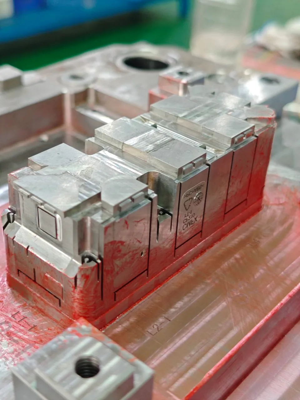
Connect tooling investment to the production plan
Production tooling is developed for repeated molding of an approved part within an agreed operating and maintenance plan. Its specification should reflect resin grade, demand, quality requirements, receiving equipment, and expected service conditions.
The lowest initial mold price does not necessarily produce the lowest part cost. Cavitation, runner choice, material consumption, cooling behavior, handling, and maintenance affect operating economics. We compare these decisions with your forecast and machine capacity so the selected construction has a clear purpose.
Bring both engineering and purchasing requirements into the review. Critical dimensions, appearance references, inspection methods, approved CAD revisions, and tool standards help avoid conflicting assumptions. If validation is still underway, rapid tooling can provide samples before the production construction is finalized.
Layout and capacity
Choose cavitation and runners together
Cavity count should fit demand, part size, shot requirements, clamp capacity, and the available molding equipment. Multiple cavities can increase output per cycle, but they also require attention to filling balance, inspection, tool size, and maintenance access.
Cold runners and hot runners create different investment and operating needs. Compare resin use, gate requirements, color changes, temperature control, and service expectations before selection. The preferred system depends on the product and production program.
Design cooling, ejection, and access as one system
Cooling layout must account for wall sections, cores, inserts, and the space available for channels. Uneven cooling can affect shrinkage and distortion; the tool layout and trial process need to address those risks together.
Ejection must release the part without unacceptable marking or deformation. Review draft, ejector contact areas, slides, lifters, and the movement sequence alongside the visible and functional surfaces.
Service access matters throughout the tool’s use. Replaceable wear components, accessible fittings, and clearly identified circuits make maintenance more practical. We review these provisions while the design can still be adjusted.
Select steel for the resin and working conditions
| Requirement | Engineering review |
|---|---|
| Wear resistance | Consider reinforced resins, sliding contact, gate areas, and replaceable components. |
| Corrosion resistance | Review the resin, processing environment, cooling water, and storage conditions. |
| Hardness and toughness | Balance working loads, slender features, heat treatment, and the ability to repair the tool. |
| Polish or texture | Match steel and surface preparation to the agreed appearance reference, including draft and release requirements. |
Prehardened and hardened steels serve different combinations of geometry, processing, and expected use. Material grade, heat treatment, and any surface treatment are selected for the project. We agree the relevant verification records as part of the delivery scope.
Tooling transfer
Confirm the receiving machine before design release
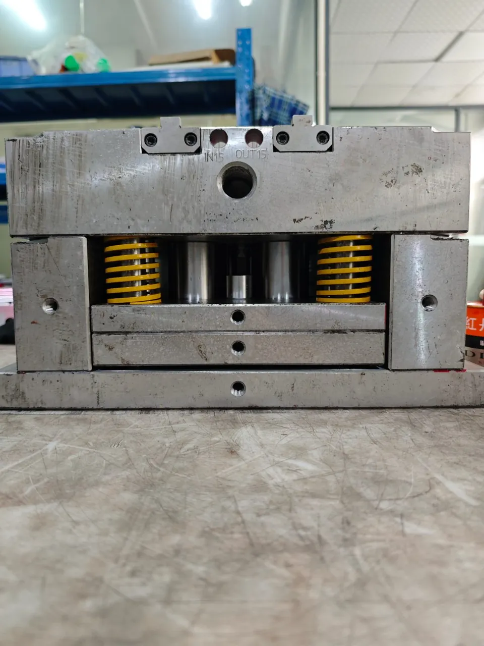
A transferable mold must fit more than the machine’s nominal tonnage. Provide the receiving machine specification and your plant’s tooling standards during the technical review. This information shapes the mold envelope, connections, and mounting arrangement.
Mechanical interfaces
Check platen dimensions, tie-bar clearance, mold height, opening stroke, locating arrangement, and clamp locations. Review ejection interfaces and lifting provisions.
Injection interface
Confirm nozzle contact, sprue interface, shot capacity, and the material processing requirements. Identify any machine-specific limits that affect the design.
Utilities and controls
Agree cooling fittings and circuit identification. Where relevant, confirm hot runner electrical connections, controller requirements, sensors, and hydraulic or pneumatic services.
For molding at YIOT, the tool and processing plan are matched to suitable equipment within our 49 automated presses, ranging from 90 to 1,200 tons. Transfer projects use the receiving facility’s confirmed requirements.
Trial, correct, and approve with a defined record
Agree the trial resin, sample quantities, dimensional inspection, cosmetic references, and approval responsibilities before sampling. The trial reviews filling, release, part appearance, and the measurements that matter to your assembly or product.
Tool component machining accuracy is one input to part quality. Molded dimensions also respond to resin shrinkage, geometry, cooling, and processing conditions. Sample inspection therefore checks the output directly against the agreed drawing and method.
Record trial findings, decide the necessary corrections, and review the resulting samples. Part approval and shipment authorization follow the project acceptance criteria. A transfer project also needs an agreed approach to setup and commissioning at the receiving site.
Plan maintenance and spare parts
Review likely wear areas and the components that should be replaceable. Ejector parts, inserts, seals, fittings, and runner components may need different service provisions depending on construction.
Agree the spare parts scope, identification, and maintenance information during the project. Inspection, cleaning, lubrication where specified, cooling circuit care, and storage protection support continued tool operation. Maintenance intervals should reflect use and condition.
Agree the handover package
The delivery package is defined for each project. It can include DFM and design records, relevant steel and hardness records, trial information, sample inspection results, component information, and the agreed packing and shipping records.
Confirm file formats, document revisions, identification requirements, packing protection, and delivery responsibilities before handover. Clear records help the receiving team understand the tool and prepare the first setup.
For the engineering review behind your tooling plan, explore DFM & Engineering and our Facility & Quality.
Production tooling questions
How do you determine the cavity count?
We review demand, part and shot size, runner balance, machine capacity, and production economics. More cavities must fit the whole operating plan.
Do production molds always need hot runners?
No. Cold and hot runners are compared against resin, gate needs, material use, investment, and maintenance expectations.
Which steel should we specify?
Share the resin grade, expected use, surface requirements, and tool standards. We review wear, corrosion, hardness, toughness, and repair needs before proposing a grade.
Can you build to our molding facility’s standards?
Provide your standards and machine information with the inquiry. We review their requirements and confirm the agreed specification before design release.
What determines tool acceptance?
The project criteria define sample inspection, appearance, functional checks where required, correction closure, and the approvals needed before delivery.
What documents and spares come with the mold?
The quotation and project agreement define them. Confirm the records, file formats, spare components, and shipping information your receiving team needs.
Build your production tooling specification with YIOT
Send approved CAD, drawings, resin grade, demand, and machine or plant standards. With complete inputs, YIOT provides a quotation response within 24 hours. Full DFM and the manufacturing schedule are agreed for the project; an NDA is available as needed.
Request a production tooling quoteView mold manufacturinggerry.li@aiyiot.com · NDA available when required.