YIOT company logoYIOT TECHNOLOGYENGINEERING · TOOLING · MOLDING

ENGINEERED AROUND YOUR PART

Automotive Injection Molding & Mold Manufacturing

Develop custom automotive plastic components with integrated engineering, mold manufacturing and injection molding. We support conventional and electric vehicle applications, from prototype evaluation to repeat production.

Illustrative process example

01 / APPLICATIONS

Plastic components.
Vehicle-wide possibilities.

Every location brings a different set of conditions. Start with the component’s function, installation environment and visible surfaces, then translate those needs into a practical material and tooling approach.

Automotive plastic component application mapSide profile of a vehicle showing interior, exterior, functional and EV component regions. Use the four links beneath the diagram to explore each application. 1234
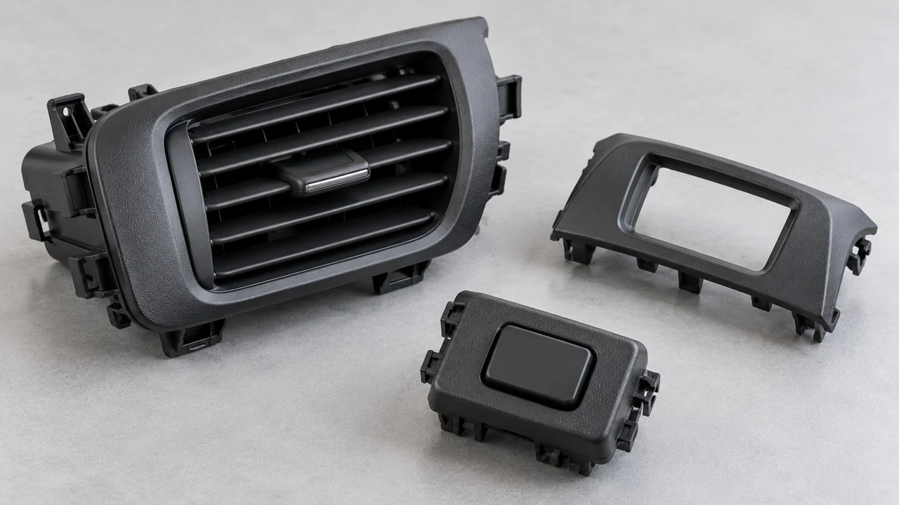
Illustrative automotive air vent, control-panel bezel and button housing
Illustrative application example

01 / INSIDE THE CABIN

Interior components

Air vents, control panel bezels, buttons, covers and brackets balance appearance with everyday handling. We review visible finish, snap-fit behavior and wall transitions together, looking for sink and warpage risks before the tool design is finalized.

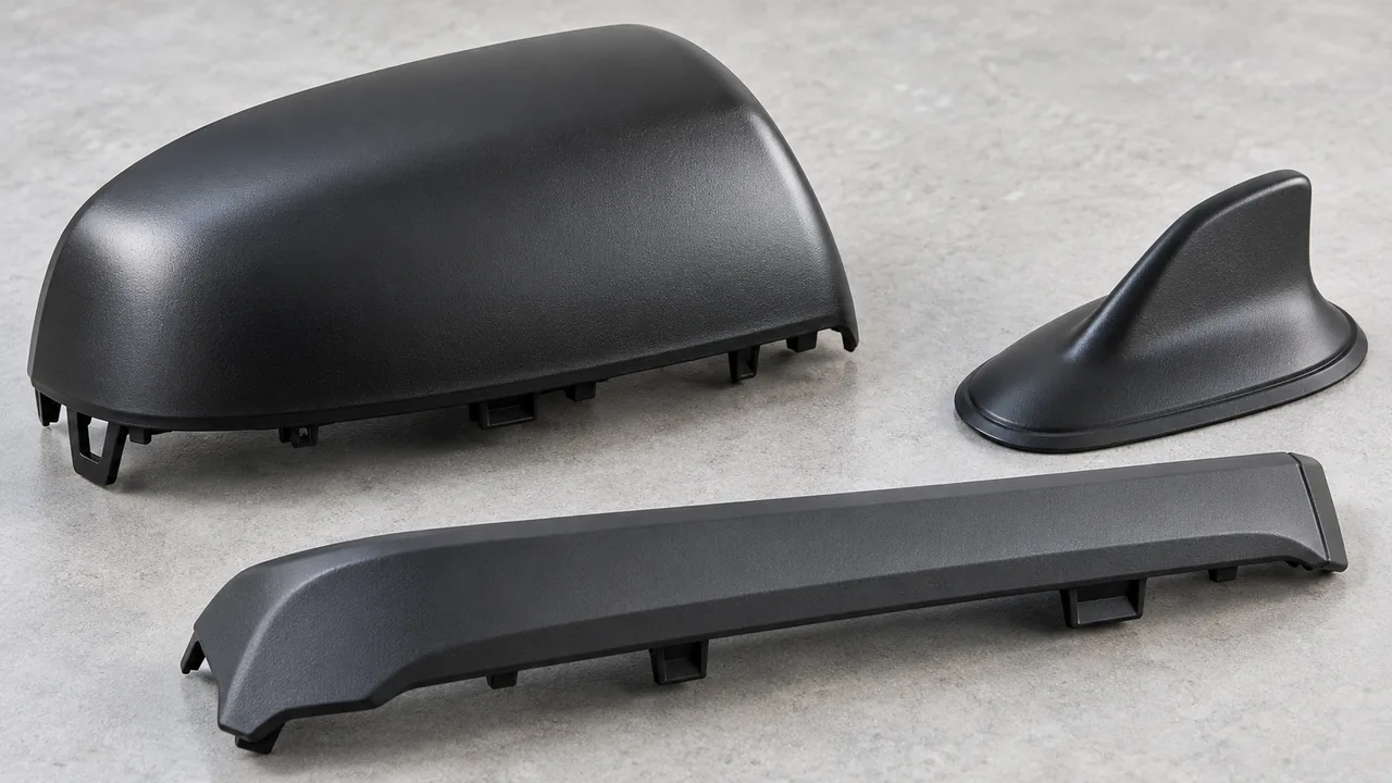
Illustrative automotive mirror cover, antenna housing and protective trim
Illustrative application example

02 / EXPOSED TO THE ELEMENTS

Exterior components

Mirror components, antenna housings, protective covers and grille brackets need a clear definition of exposure and installation loads. Material discussions consider UV and weather resistance, surface expectations and fastening geometry, with validation requirements agreed for the intended environment.

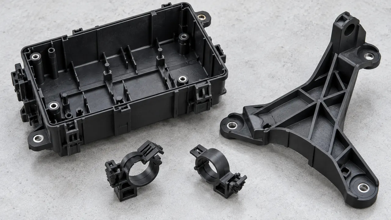
Illustrative automotive fuse-box housing, mounting bracket and cable clips
Illustrative application example

03 / BUILT TO SUPPORT

Functional & underhood parts

Wire holders, fuse box components and mounting brackets must suit their surrounding conditions. Heat, contact with media and vibration inform grade selection. For reinforced materials, fiber orientation and shrinkage need attention because they can influence stiffness, dimensions and assembly behavior.

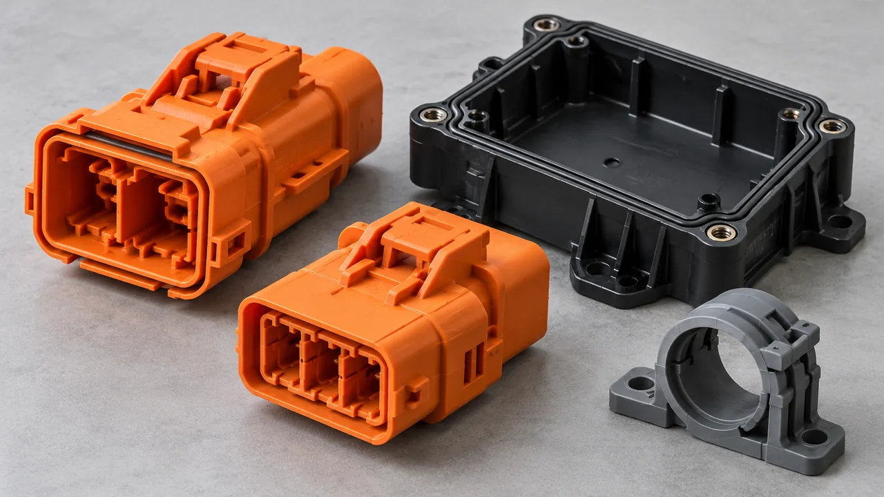
Illustrative EV connector housings, electronic enclosure and cable clamp
Illustrative application example

04 / CONNECTING ELECTRIC SYSTEMS

EV & electrical components

Charging connector housings, terminal retention features, ECU covers and cable holders put emphasis on material grade, electrical requirements and interface dimensions. Insert position, seal contact areas and retention geometry are reviewed against your drawings and the component’s intended assembly.

02 / ONE CONNECTED WORKFLOW

From Prototype Parts
to Production Tooling

Choose a development route that matches the decisions still to be made. Carrying feedback forward helps align the part, mold and molding process before repeat orders begin.

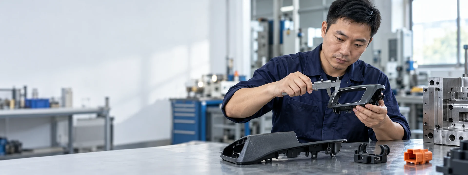
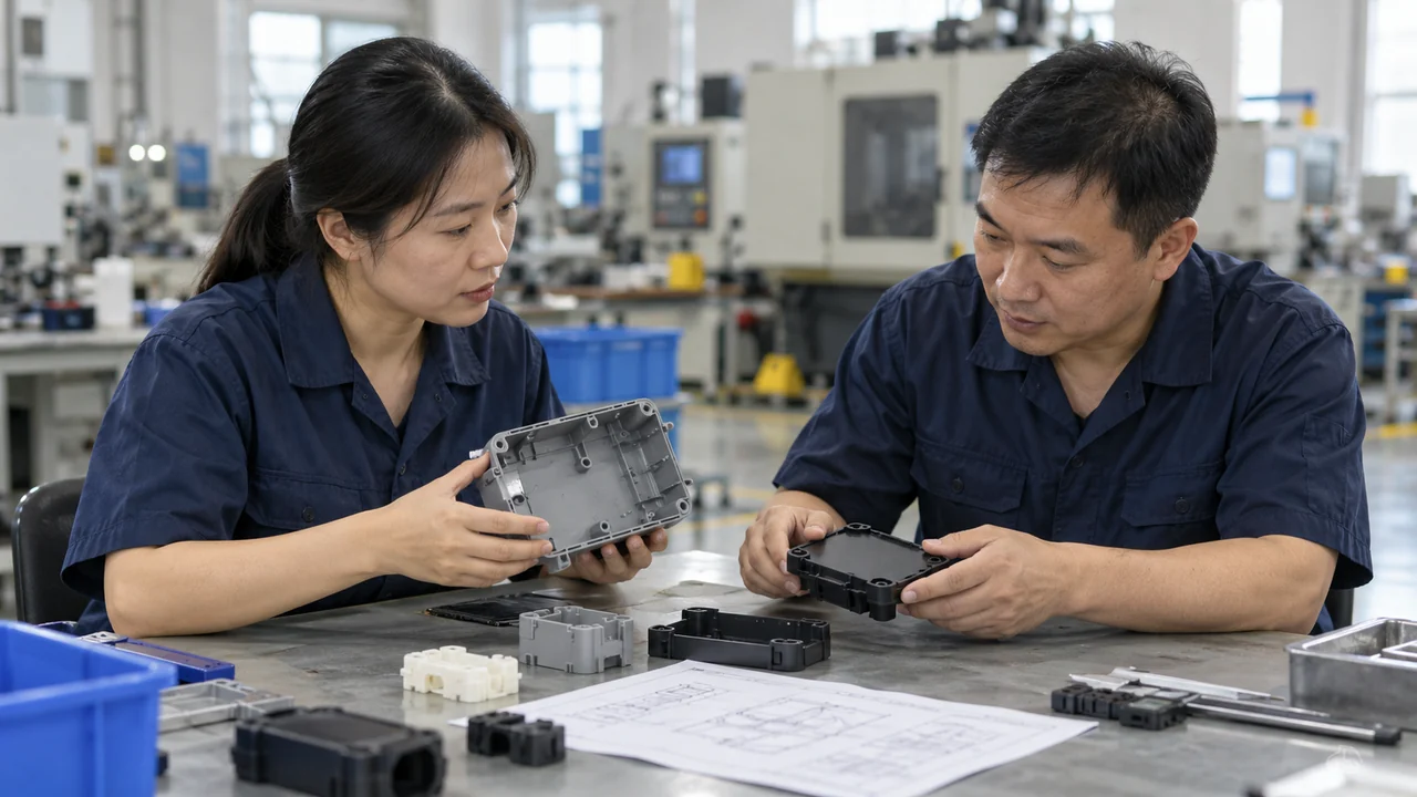
Illustrative engineering review of automotive housing prototype fit
Illustrative process example
  1. 01

    Evaluate the prototype

    Use prototype parts to evaluate fit, access and assembly sequence. Record what the prototype can demonstrate and what still needs molded material or production tooling to confirm.

  2. 02

    Define the tooling route

    Compare rapid tooling with production tooling using quantity, geometry, material and expected changes. Confirm cavity layout, tool interfaces and the approval stages for the selected route.

  3. 03

    Mold, finish & assemble

    Connect injection molding with the required finishing and assembly. Trial feedback establishes agreed settings, appearance references and handling requirements for the next production stage.

A prototype’s appearance does not automatically establish production performance. We distinguish geometry checks from material and process questions, so each stage answers a defined set of questions. If your design is still changing, share the likely revisions early; they may affect how the tooling is arranged and when particular features should be finalized.

03 / DETAILS THAT SHAPE THE RESULT

Engineer the interfaces
before cutting steel.

A bracket or housing is a network of connected features. Our DFM review brings manufacturing questions into the design discussion while changes are easier to make.

Provide mating components or their interface drawings wherever possible. A local feature that looks acceptable in isolation can affect assembly clearance, visible alignment or load transfer. We discuss those relationships alongside manufacturing access, then document the design decisions that need your approval before the next stage.

Six design review locations on a molded housingAn original engineering illustration of a shallow housing with ribs, snap features, a gate location, mounting interfaces and an insert boss. The six numbered checks beside the drawing describe the review topics. 123645
Design review illustration · geometry shown for explanation
  1. Wall & rib balance

    Review thickness transitions, rib proportions and local mass for filling, cooling and sink risk.

  2. Snap-fit & assembly

    Consider engagement, release, deflection and assembly access in the selected material.

  3. Draft & parting

    Align draft, parting lines and ejection with function and surfaces that remain visible.

  4. Gate & appearance

    Discuss the illustrated gate tab, flow direction and potential weld line locations against appearance priorities.

  5. Insert retention

    Define insert location, support, retention geometry and how position will be checked.

  6. Shrinkage & warpage

    Review dimensional relationships, restraint and reinforcement orientation at mating interfaces.

04 / MATERIAL DECISIONS

Select the grade.
Then design around it.

Polymer families are a starting point. Final selection depends on the grade’s data, the component’s requirements and any agreed validation. Share an existing specification where one applies.

Material families for automotive plastic component discussions
Material familyTypical applicationsWhat to confirm
PPCovers, trim and wire managementStiffness, impact behavior, shrinkage and the need for UV stabilization.
ABS / PC-ABSInterior bezels, control surrounds and housingsSurface finish, heat exposure, impact requirements and grade-specific processing.
PABrackets, clips and functional housingsMoisture conditioning, heat and media exposure; reinforcement effects on dimensions.
PBTConnector and electrical housingsElectrical requirements, moisture handling, reinforcement and the specified grade.
POMMoving features, guides and retention partsFriction, dimensional needs, chemical exposure and restrictions on bonding or finishing.
TPE / TPUSoft-touch features, flexible covers and interfacesHardness, environmental exposure, compression needs and adhesion to the chosen substrate.

A family name alone cannot define an automotive application. Filled and unfilled grades can behave differently, and colorants or additives may influence processing and performance. Where electrical, flame, weathering or chemical requirements apply, identify the exact specification and acceptance criteria. We use those inputs to guide the material discussion and identify questions that require supplier data or project-specific validation.

05 / APPEARANCE & ASSEMBLY

Appearance. Fit.
Multiple materials.

Bring color, texture and assembly requirements into the initial review. A visible housing may need controlled cosmetic zones, while an internal bracket may prioritize retention and access. Mark critical surfaces and mating parts on the drawing.

Insert molding can integrate specified metal features. Overmolding and two-shot molding can combine material functions where geometry and material compatibility support the approach. We review insert positioning, interface design and adhesion expectations with you before proposing a tooling concept.

06 / AGREED CRITERIA, VISIBLE CHECKPOINTS

Quality starts with
a shared definition.

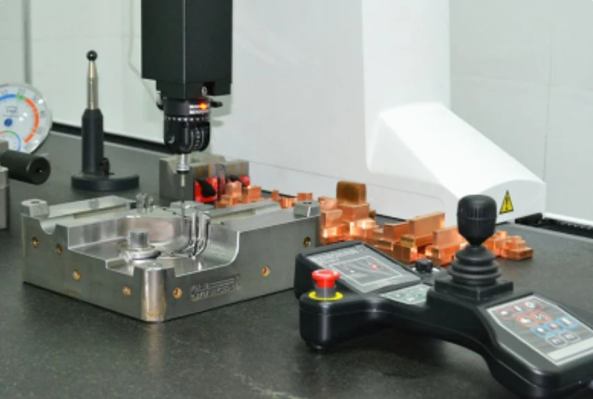
Inspection planning follows the part’s requirements. Agree dimensional, appearance and assembly checks, sampling and records for the project, with special attention to features that affect the next operation. Project-agreed deliverables may include a DFM review or report, mold design confirmation, a mold trial record or report, and a dimensional inspection report. Confirm the required documents and approval points for your project.

Coordinate measuring equipment in the Dongguan factory inspection area
YIOT factory inspection environment
  1. 01

    Requirements

    Confirm drawings, the agreed DFM review or report, and mold design confirmation before the relevant tooling stage.

  2. 02

    Trial review

    Review samples and the agreed mold trial record or report against dimensional, appearance and assembly criteria.

  3. 03

    Production checks

    Apply the project’s inspection plan, including the agreed dimensional inspection report, and review relevant changes before further production.

  4. 04

    Dispatch review

    Confirm agreed records, quantity, packaging and identification for the shipment.

The drawing and approved references form the basis for review. Where a requirement is ambiguous, we clarify the datum, measurement condition or cosmetic boundary before relying on it for acceptance. Changes to material, geometry or agreed finishing should return to the project review so their effect on fit and appearance can be considered. Explore our facility and quality approach for more context.

07 / PROJECT EXPERIENCE

From requirement
to manufactured part.

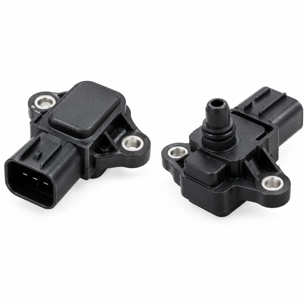
Automotive sensor enclosure tooling — existing catalog image

EXISTING CATALOG EXAMPLE

Automotive sensor enclosure tooling

This existing catalog example concerns custom injection molds for plastic automotive sensor enclosures. Review housing geometry, mounting interfaces and the fit of mating components during DFM. Material grade, critical dimensions and the acceptance plan are defined from the customer’s drawing for each new project.

View project example
Automotive air-filter component tooling — existing catalog image

EXISTING CATALOG EXAMPLE

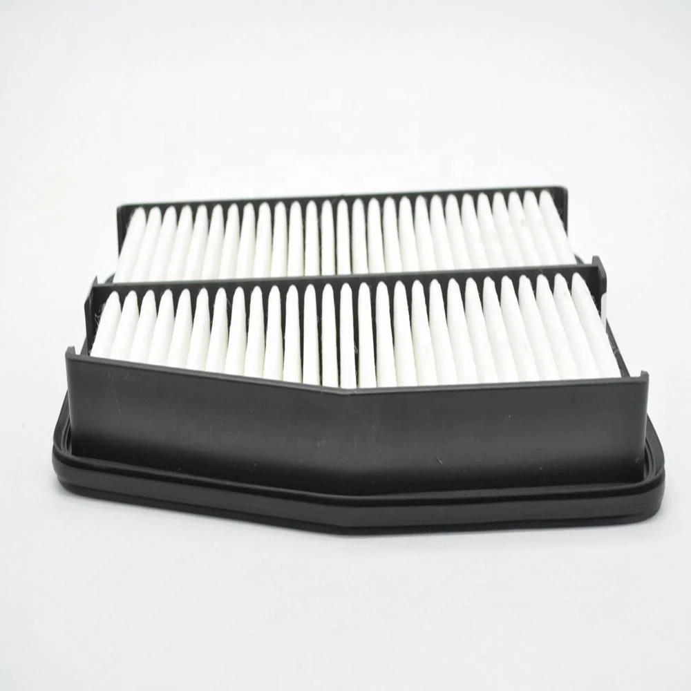
Automotive air-filter component tooling

This catalog example covers tooling for automotive air-filter components. The part drawing establishes the required frame geometry and interfaces. Mold development connects DFM, machining and assembly with trial review; material, operating conditions and inspection requirements are agreed for the application.

View project example

08 / PROJECT QUESTIONS

Before we begin.

What information should I send for a quote?

Send 3D files, drawings, quantity, material requirements, finish, mating interfaces and target timing. Highlight critical dimensions and any customer specifications.

Can you help with material selection?

We can discuss suitable families and grades against your requirements. Final selection and validation should address the actual operating environment and applicable specifications.

When should we consider insert, overmolding or two-shot molding?

Consider these routes when integrated features or combined material functions support the design. Compatibility, retention, geometry and volume determine whether the approach is practical.

How does a prototype move into production?

Review prototype feedback, update the design and agree the tooling route. Molded trials then support approval of the part and production requirements.

How are dimensions and appearance agreed?

Identify critical dimensions, cosmetic zones and assembly checks before tooling. Agree inspection methods and sample references as part of the project review.

What timing can I expect, and is an NDA available?

An NDA is available. We aim to quote within 24 hours after receiving complete information; DFM depth and the full development timeline are agreed by project.

LET’S REVIEW YOUR REQUIREMENTS

Discuss Your Next
Automotive Parts Project

Share your part files and priorities. We will help define the next practical step. We aim to quote within 24 hours after receiving complete information; DFM depth and the full timeline are agreed by project.

Request an Automotive Quote
Gerry Ligerry.li@aiyiot.com+86 137 9038 6386Chat on WhatsApp NDA available · Project-defined DFM and timing