
Validate with injection molded parts
Rapid Tooling for Injection Molding
Move from a digital design to molded parts for functional testing, assembly checks, and small production runs. YIOT builds rapid and prototype injection molds around the decisions you need to make before committing to a larger production program.
We review the intended resin, geometry, finish, and expected use to select an appropriate mold construction. Supply can include a transferable tool or sampling and molding at YIOT.
Discuss your prototype tooling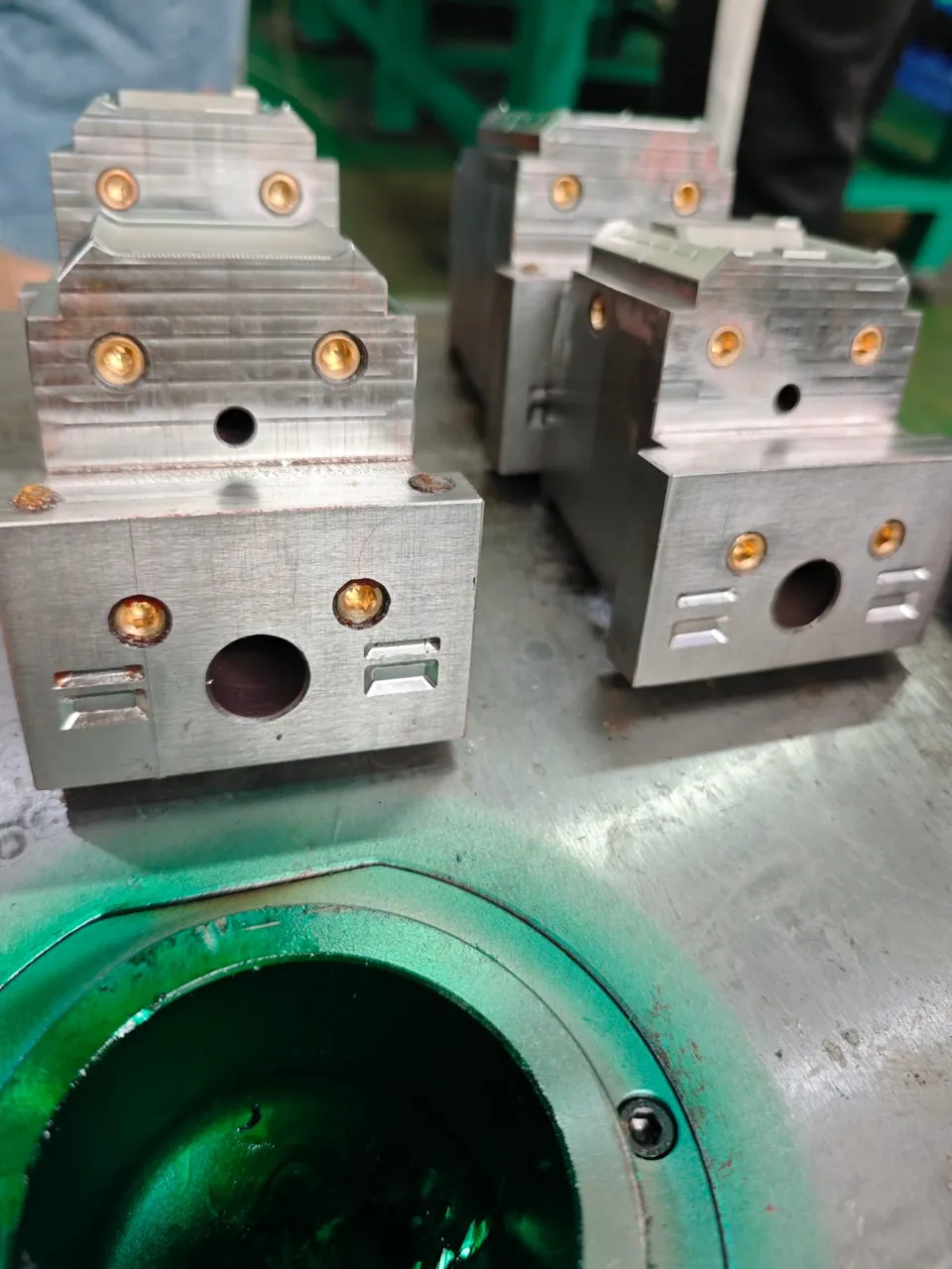
What rapid tooling helps you prove
Rapid tooling is an injection mold developed with a focused construction and manufacturing scope for a defined project need. It can produce parts in the intended molding resin, helping engineers assess behavior that depends on material, geometry, and the molding process.
Functional performance
Check stiffness, snap features, seals, handling, or other functions using your test plan and the specified material.
Assembly and fit
Evaluate interfaces with mating components, fasteners, inserts, and real assemblies. Mark the dimensions that govern acceptance.
Smaller runs and bridge supply
Support pilot builds or limited demand while product design and purchasing requirements develop. Review repeat orders against tool condition and capacity.
Define the learning objective before approving the mold. A sample intended for an assembly check may need a different finish or inspection scope from one intended for customer appearance approval. These choices help direct the investment toward useful evidence.
Material selection
Aluminum or prehardened steel?
Aluminum can suit selected rapid tooling applications where machining access, heat transfer, and the planned use support the choice. Prehardened steel is an alternative when part features, resin, loading, or expected reuse call for a different balance of machinability and durability.
Selection depends on the actual project. Reinforced resins, corrosive processing conditions, thin features, slide contact, and demanding surfaces deserve specific review. We assess those factors before proposing a material; a universal part quantity or mold lifespan would not describe every application.
Compare the purpose of each tooling route
| Decision | Rapid tooling | Production tooling |
|---|---|---|
| Primary purpose | Validation, pilot builds, and defined smaller runs. | Repeatable output for an established production program. |
| Design maturity | Often accommodates a design still being evaluated. | Usually follows approval of the product design. |
| Construction priorities | Focused investment and practical access for expected revisions. | Capacity, operating efficiency, wear resistance, and maintenance. |
| Cavities and runners | Selected to serve the validation and supply plan. | Selected around demand, material use, and production economics. |
| Future use | Reviewed against tool condition and changing requirements. | Planned with ongoing service and spare components in mind. |
A simpler mold still needs proper engineering
Rapid tooling can use a simpler mold base, cavity arrangement, or runner system when appropriate. Cooling, venting, gate placement, and ejection still require attention: they affect filling, part release, surface marks, and dimensional consistency.
DFM reviews wall sections, draft, undercuts, and the features that must be measured. Replaceable inserts may help isolate a likely design change, but revision access must be considered before machining. Moldflow analysis can be included when a specific filling or flow question warrants it.
Five steps to useful molded samples
Define the validation task
Share CAD, resin grade, drawings, sample demand, and the functions or surfaces you need to assess.
Agree the tooling concept
Review material, cavities, runners, revision options, and the molding or transfer route.
Review and manufacture
Complete the agreed DFM and design approval, then machine, fit, and assemble the tool.
Trial and inspect
Produce samples in the agreed resin and document the agreed dimensions and appearance observations.
Review the next decision
Approve parts, request a defined revision, plan another run, or prepare production tooling.
Review samples against your test plan
Agree the sample quantity, inspection points, and test responsibilities before trial. Molded part tolerances depend on resin shrinkage, geometry, and process conditions as well as tool manufacture. Use measured parts and assembly checks to establish whether the design meets its intended purpose.
Make changes with a controlled revision
After review, identify the change in the CAD and drawing revision. We assess its effect on the existing tool, sampling, and schedule. Some features permit local modification; others require a new insert or a different construction.
Carry the learning into production tooling
Approved sample geometry, observed filling behavior, assembly feedback, and confirmed cosmetic requirements provide a stronger basis for the next mold. Production tooling may need different cavitation, runners, cooling, steel, or service provisions.
We review that transition with your purchasing and engineering teams. Rapid tooling does not automatically become the production mold; the next construction should fit the approved demand and manufacturing plan.
Plan production toolingFor the engineering review behind your tooling plan, explore DFM & Engineering and our Facility & Quality.
Rapid tooling questions
Can we use our intended production resin?
Share the exact grade and any reinforcement or additives. We review its processing and tooling requirements before confirming the material and sampling plan.
Is aluminum always the fastest choice?
No. Geometry, stock availability, finish, resin, and construction all affect the project. We compare aluminum and steel against the work required.
How many parts can a rapid mold produce?
The practical range depends on construction, resin, part features, process, and maintenance. We agree the intended use during review.
Can the tool be revised after sampling?
We assess each requested change. Replaceable inserts or local modifications may help, while some changes need more extensive rework.
Can we transfer the mold to our own molder?
Yes. Provide the receiving machine details and tool standards early so interfaces, documentation, and delivery can be agreed.
When do full DFM and sampling take place?
Initial quotation review comes first. Full DFM, design release, manufacture, and sampling follow the scope and timing agreed for your project.
Tell us what your next samples must prove
Send your files, resin, sample quantity, and validation objectives. With complete inputs, YIOT provides a quotation response within 24 hours. An NDA can be arranged as needed.
Request a rapid tooling quotegerry.li@aiyiot.com · NDA available when required.