
Metal features · Plastic structure
Insert Molding Services
Integrate threaded inserts, terminals, and bushings into a molded plastic component with positioning, retention, and assembly requirements considered from the start.
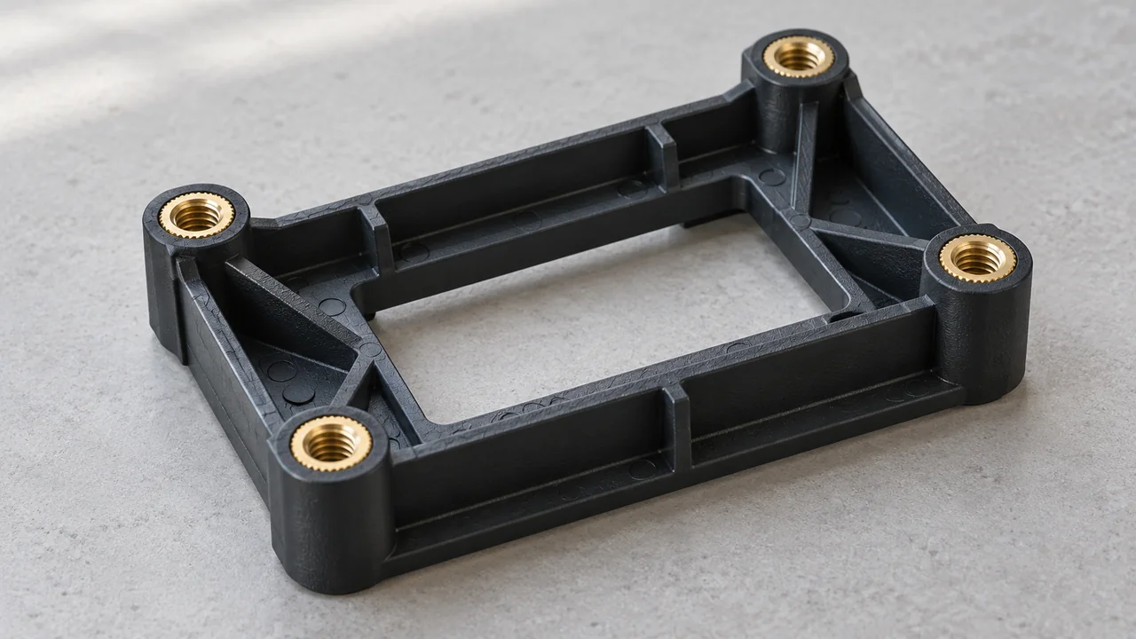
One component. Two materials.
Make the insert part of the structure
Insert molding places a prepared insert into the mold before plastic is injected around it. The finished component combines the insert’s function with the surrounding plastic geometry.
Yiot Technology provides insert molding in-house alongside mold manufacturing and conventional injection molding. We review insert drawings, resin selection, loading access, and final-part inspection together. The objective is a production route that consistently locates the insert and protects the surfaces needed for assembly or electrical contact.
An insert may be metallic or another suitable preformed component. Suitability depends on how it behaves under the molding temperature and pressure, how it is held in the cavity, and how the materials interact during cooling and use.
01 / Application features
Common reasons to mold around an insert
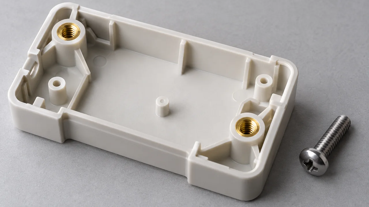
Threaded connections
Metal threads support repeated assembly or defined fastener loads. The plastic around the insert must provide adequate retention without creating excessive local wall thickness.
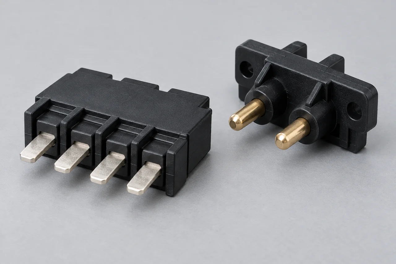
Terminals & contacts
Conductive features can be located within an insulating plastic body. Contact areas, exposed dimensions, and any electrical requirements need clear specifications.

Bushings & sleeves
A sleeve can support a locating, bearing, or fastening function. Position, concentricity, and the relationship to adjacent plastic features guide the tooling approach.
02 / Retention geometry
Design the interface for the load
Insert retention needs more than plastic surrounding a smooth surface. Knurls, grooves, shoulders, or other designed features may help resist rotation or axial movement.
We review anti-rotation and pull-out requirements against the insert shape, embedment, resin, wall geometry, and service conditions. The appropriate feature arrangement depends on the direction and magnitude of the applied load. Where a fastening load is important, define the assembly torque, fastener type, engagement length, and expected assembly cycles.
Metal and plastic can respond differently to cooling and temperature changes in service. Local shrinkage and stress around an insert can contribute to cracking or dimensional change. Material choice, surrounding wall design, insert edges, and process conditions are therefore reviewed together.
03 / Positioning & protection
Hold what must stay in place
The mold must locate the insert before injection and support it against pressure during filling. A stable loading method is essential to the finished part’s consistency.
Locate the insert
Review datums, seating faces, loading direction, and how the tooling detects or prevents incorrect placement.
Protect the thread
Define which threaded, contact, or bearing surfaces must remain free from plastic. Shut-off geometry and support details need review.
Manage pressure
Consider gate position, flow direction, insert stiffness, and support to reduce movement or distortion during filling.
Flash around a protected surface, shifted inserts, incomplete fill, or cracks can indicate different tooling and processing issues. Inspection should target these risks instead of relying only on a visual check of the plastic exterior.
04 / Process route
Prepare. Position. Mold. Check.
- PrepareConfirm insert dimensions, condition, identification, and cleanliness requirements.
- PositionLoad and seat the insert against the mold’s locating features.
- MoldFill and cool the plastic around the insert within the agreed process window.
- EjectRelease the component without damaging the insert or surrounding plastic.
- CheckVerify location, protected surfaces, appearance, and agreed functional criteria.
Insert supply is part of the production plan. Confirm who sources the inserts, required incoming checks, packaging, lot identification, and any handling precautions. A variation in insert dimensions or finish can affect seating, flash control, and retention even when the plastic tool remains unchanged.
During trials, we review the molded component with its assembly context. First samples help confirm tooling access, insert position, plastic coverage, and the measurement method before repeat production is approved.
05 / Compare the alternatives
Molded-in or installed after molding?
| Consideration | Molded-in insert | Heat-installed insert |
|---|---|---|
| Process sequence | Insert loaded before plastic injection | Suitable insert installed into a molded receiving feature afterward |
| Design focus | Location, encapsulation, support, and pressure resistance | Receiving-hole geometry, installation access, and local plastic flow |
| Production handling | Insert loading coordinated with the molding cycle | Additional installation operation and inspection |
| Selection basis | Integrated geometry and project retention requirements | Assembly sequence, access, volume, and installation feasibility |
Neither route is automatically the better choice. Compare total handling, tool complexity, insert design, assembly access, and the required torque or pull-out performance. A DFM review can help evaluate the geometry before committing to the mold.
Project questions
Insert molding FAQ
What types of inserts can be considered?
Common candidates include threaded inserts, terminals, sleeves, and bushings. Send the insert drawing and material specification so we can review temperature resistance, location, and mold support.
Can an insert move during molding?
Yes. Injection pressure and flow can move an inadequately supported insert. Tooling location, gate layout, insert rigidity, and trial results guide the support design.
How are threads protected from plastic?
The tooling is designed around the surfaces that must remain exposed. The protection method depends on insert geometry and access; thread cleanliness and flash criteria should be part of acceptance.
Do you check torque or pull-out strength?
These checks can be included when the test method, load criteria, sample quantity, and conditioning are agreed. Values are specific to the insert, resin, geometry, and intended use.
Can I supply my own inserts?
Customer-supplied inserts can be reviewed. Agree on dimensional specifications, incoming inspection, lot identification, quantity allowance, and delivery timing before production.
What does an insert molding quote need?
Provide part and insert drawings, resin requirements, quantity, assembly loads, exposed surfaces, and inspection criteria. We aim to respond within 24 hours with complete inputs; detailed review timing is project-specific.
Continue your review
Related molding services
Quote preparation
Send the part and the insert together
Share the complete interface so we can review loading, retention, and tooling needs. An NDA is available when needed.
Request an insert molding quote- 3D part model and dimensioned drawing
- Insert drawing, material, finish, and supply plan
- Plastic grade and expected production quantity
- Critical insert positions and protected surfaces
- Assembly torque, pull-out, or other test requirements
- Appearance, inspection, and documentation criteria