Rigid structure · Added function
Custom Overmolding Services
Add a grip, soft-touch surface, protective layer, or sealing feature to a molded substrate with the material interface designed for its actual working conditions.
Function at the surface
A second material with a defined job
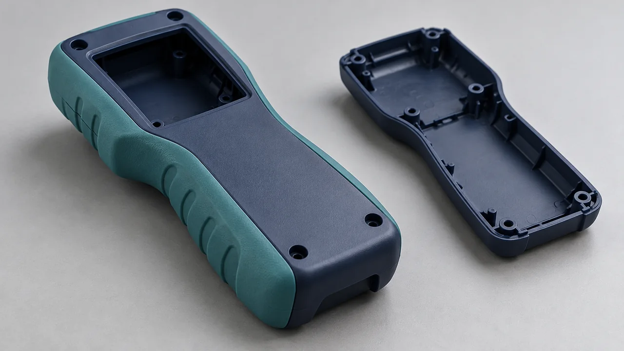
Overmolding forms an additional material over a prepared substrate. The substrate provides the underlying structure; the added layer provides the surface or functional feature specified by your design.
Yiot Technology supports overmolding in-house, with mold manufacturing and process review coordinated around both materials. We examine substrate location, layer thickness, exposed boundaries, gate access, and the conditions needed to achieve the intended interface.
Soft material does not automatically create a seal, and two materials do not automatically bond. The exact grades, geometry, processing conditions, and service environment determine what can be achieved. These are reviewed before tooling approval and checked during trials.
01 / Application features
Where the added layer earns its place
Tool & equipment grips
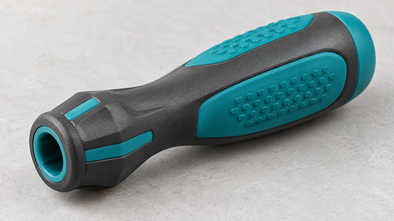
A soft layer can change the contact surface and handling feel. Define grip geometry, hardness, wear expectations, and exposure to oils or cleaners.
Electronic housings
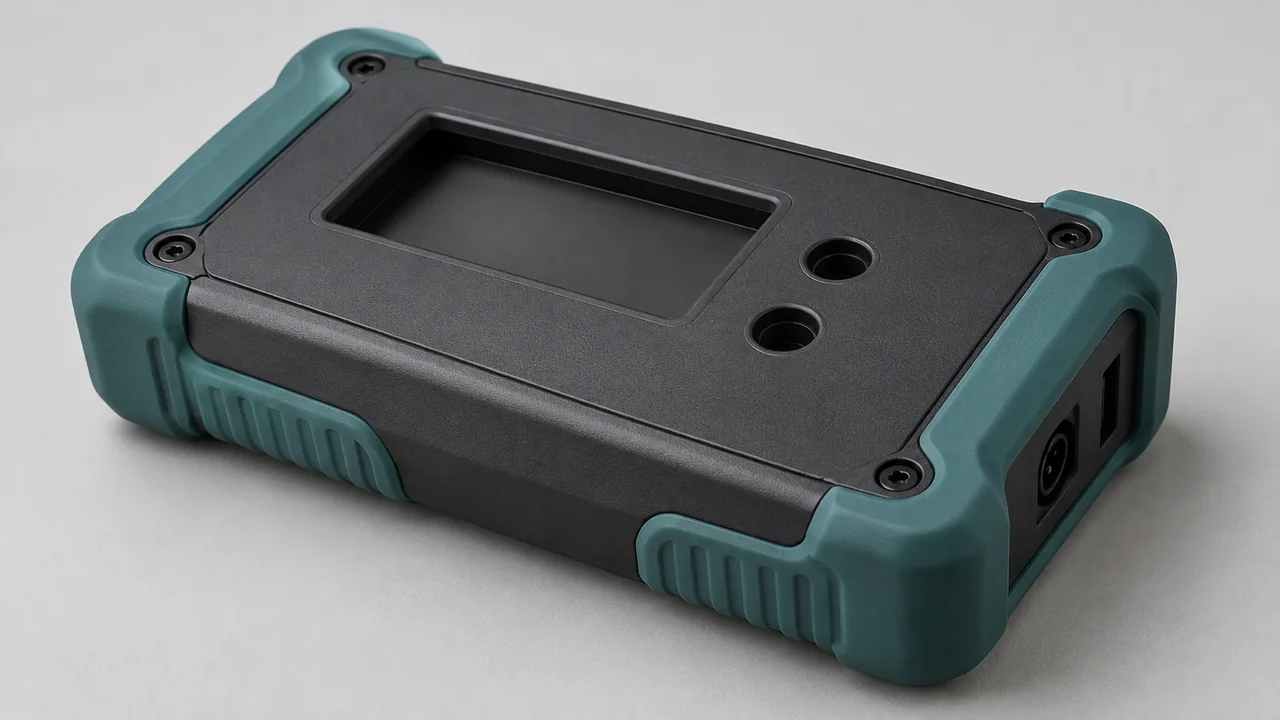
Selected surface zones may add cushioning, grip, or protection. The housing’s fit, visible boundaries, and assembly clearances must remain controlled.
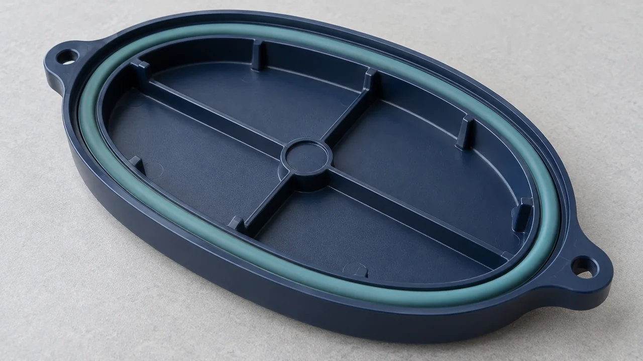
Sealing structures
A molded flexible feature can be designed around a mating surface. Compression, contact geometry, environment, and the agreed leak or function test establish acceptance.
02 / The material interface
Substrate. Soft layer. Finished component.
Begin with the rigid substrate, define where the second material must sit, then verify how the finished interface performs. Each stage introduces its own design requirements.
Substrate
The prepared rigid part establishes the supporting geometry.
Soft layer
The second material fills the designed surface region.
Finished component
Inspect the boundary and verify the intended function.
Some compatible material pairs can develop adhesion during molding. That depends on the exact grades and processing conditions, not simply a family name such as “TPE” or “ABS.” Supplier guidance helps shortlist candidates; trials and agreed testing confirm whether the selected pair meets your requirements.
Mechanical locking uses designed geometry such as openings, undercuts, or capture features to retain the added material. This can complement adhesion or provide retention where appropriate, but it must be checked against flow, tooling access, assembly loads, and service conditions.
03 / Material definition
Specify the pair, not just the softness
| Input | What to define | Why it matters |
|---|---|---|
| Substrate grade | Exact resin, reinforcement, additives, and color | Influences compatibility, stiffness, and dimensional behavior |
| Soft-layer grade | TPE, TPU, or other specified material and supplier grade | Sets processing requirements and candidate bonding behavior |
| Hardness | Target scale, value, and acceptable range | Affects feel, flexibility, compression, and geometry choices |
| Environment | Temperature, fluids, UV, wear, and cleaning exposure | Defines the conditions the interface must withstand |
| Cleanliness | Handling, storage, contamination, and surface preparation limits | Contamination can affect appearance and adhesion |
| Verification | Bond, peel, pull, compression, or function test as applicable | Connects the material choice to measurable acceptance |
Hardness alone does not predict grip, durability, or seal performance. Discuss the complete function and provide a reference sample where the feel or appearance is difficult to describe in a drawing.
04 / Boundary control
Keep the second material where it belongs
Shut-off surfaces define the edge of the overmold. The substrate and tool must seat consistently enough to contain the second material without damaging the first component.
Delamination
Review grade compatibility, interface design, substrate condition, and processing when the layers separate.
Flash & short shots
Check substrate seating, shut-off geometry, material flow, venting, and fill behavior at thin or remote features.
Warpage
Consider substrate support, heat exposure, cooling, and differential shrinkage between the materials.
We review visible material boundaries and functional contact surfaces separately. A cosmetic line may have one acceptance standard, while a sealing lip or assembly interface needs a test linked to its intended use.
05 / Production route
Transfer overmolding or two-shot molding?
| Factor | Transfer overmolding | Two-shot molding |
|---|---|---|
| Substrate handling | Prepared substrates are transferred and loaded into the overmold tool | First and second shots are coordinated in a two-material molding cycle |
| Tooling & equipment | Requires locating and support for the transferred substrate | Requires suitable dual-unit equipment and coordinated mold architecture |
| Changes | Separate stages can provide flexibility for substrate or production changes | Changes may affect the coordinated two-shot tooling and sequence |
| Economics | Evaluate loading, storage, inspection, and tooling costs | Evaluate tool investment, cycle, automation, and expected volume |
Annual demand, batch size, part geometry, handling requirements, and material compatibility influence the choice. We can review both routes because two-shot molding is also available in-house. A higher volume alone does not establish the best answer without the tooling and cycle assessment.
Project questions
Overmolding FAQ
Will the soft material bond to my substrate?
That depends on the exact grades, geometry, substrate condition, and process. We review compatibility guidance and confirm performance through project-defined trials and tests.
Can mechanical retention be used?
Yes, where the geometry and tooling support it. Openings or capture features may help retain the layer, but the design still needs evaluation for flow, stress, and service conditions.
How do I specify the soft-touch feel?
Provide the material grade if known, hardness requirements, contact geometry, and a reference sample when available. Surface texture and layer thickness also influence the finished feel.
Can overmolding create a sealing feature?
It can be considered. Define the mating surface, compression, operating environment, and leak or function criteria so the sealing geometry and material can be evaluated together.
How is the interface checked?
Visual boundary checks and relevant dimensional checks are combined with agreed bond or functional testing. The method, conditioning, and acceptance criteria depend on the component’s use.
What is needed for an overmolding quote?
Send both material specifications, CAD, layer boundaries, quantities, and performance criteria. We aim to respond within 24 hours with complete inputs; full DFM and validation timing are agreed separately.
Continue your review
Related molding services
Quote preparation
Define the surface and its function
Send the substrate and added-layer geometry together. We will review the material interface, tooling route, and quotation scope. An NDA can be arranged.
Request an overmolding quote- 3D models and drawings for both material regions
- Exact grades or required material properties
- Hardness, color, texture, and visible boundaries
- Annual demand and batch expectations
- Service environment and substrate supply plan
- Bond, sealing, or other functional acceptance tests