
Engineering support · Tooling · Production
Custom Injection Molding Services
Bring your plastic component from drawing to repeat production with a manufacturing team that considers the part, the mold, and the process together.
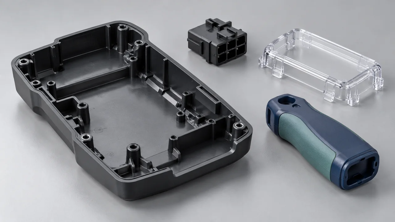
A practical path to production
Decisions made around your part
Yiot Technology supports overseas OEM procurement and engineering teams with custom injection molding, insert molding, overmolding, and two-shot molding. Our Dongguan manufacturing base brings mold making, trials, production, and inspection into the same project conversation.
We review your geometry, material, annual demand, assembly requirements, and acceptance criteria before recommending a process. That review helps expose the trade-offs behind a quote: where the tool needs movement, which surfaces need protection, and which dimensions need a defined measurement method.
A machine’s clamping tonnage alone does not establish suitability. Part size, projected area, shot volume, material behavior, cavity count, and mold construction also guide machine selection. We confirm the production route against the actual project requirements.
01 / Process selection
Four ways to build the right component
Start with the function you need. A single plastic part, a retained metal feature, a soft surface, and a two-material interface each place different demands on tooling and process control.
Injection molding
A single resin fills the mold to form the component. This is a practical route for housings, covers, brackets, connectors, and many repeat-production plastic parts.
See the molding cycle →Insert molding
Plastic is molded around a positioned insert. Threaded fasteners, terminals, and bushings can become part of the molded structure, subject to retention and positioning requirements.
Insert molding services →Overmolding
A second material is molded onto an existing substrate. The design can add grip, cushioning, protection, or a sealing feature where the material pair and geometry support it.
Overmolding services →Two-shot molding
Two injection units form a two-material component through coordinated molding stages. Tooling manages first-shot retention, indexing, alignment, and the second-material interface.
Two-shot molding services →02 / The molding cycle
From resin to a repeatable part
The mold closes, resin fills the cavity, pressure supports packing, the part cools, and the mold opens for ejection. Stable output depends on how these stages work together.
Resin preparation follows the selected grade’s requirements. During trials, fill behavior, packing, cooling, and ejection are evaluated against the part specification. Short shots, sink, weld lines, distortion, and surface variation can point to different causes; changing one setting without understanding that cause can move the problem elsewhere.
Once samples meet the agreed criteria, the approved material, tooling condition, and process window become the basis for production control. Changes are reviewed for their effect on appearance, dimensions, and function.
03 / Material choices
Choose a grade for the working environment
A resin family is the starting point. Grade, reinforcement, additives, color, drying requirements, and service conditions can change both part performance and molding behavior.
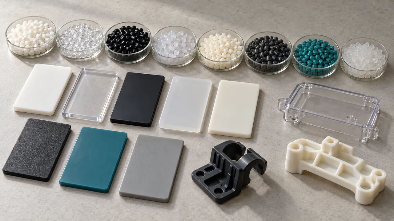
| Material | Typical design interest | Questions to resolve |
|---|---|---|
| ABS | Housings and visible components | Impact, heat exposure, color, and appearance |
| PC | Tough parts and transparent features | Optical requirements, chemical contact, and stress |
| PC/ABS | Housing applications requiring a property balance | Exact blend grade, heat, impact, and finish |
| PP | Lightweight parts and suitable living-hinge designs | Stiffness, shrinkage, assembly, and hinge validation |
| PA | Structural and wear-related components | Moisture conditioning, reinforcement, and dimensions |
| POM | Precision mechanisms and sliding parts | Wear, friction, shrinkage, and mating geometry |
| PBT | Electrical and engineering components | Grade requirements, reinforcement, and conditioning |
| TPE | Soft-touch layers and flexible features | Hardness, substrate compatibility, and environment |
| TPU | Flexible parts with wear or grip requirements | Grade, moisture preparation, chemicals, and bonding |
Specify the exact approved grade when one exists. Where substitution is possible, we discuss equivalent candidates and validation requirements with your team before a material change.
04 / Design for manufacturing
Review the features that determine moldability
A useful DFM review connects geometry to the intended production method. We identify issues early enough for your team to make an informed design decision, with the scope and timing of a full review agreed for the project.
Walls & transitions
Review thickness changes, filling paths, and cooling differences that may contribute to sink or distortion.
Ribs & bosses
Balance stiffness and assembly support with wall intersections, local mass, and access for tooling.
Draft & release
Consider draw direction, texture, undercuts, and ejection so the part can leave the mold without damage.
Gates & weld lines
Discuss gate position, visible vestiges, fill balance, and weld-line locations in relation to function.
Critical dimensions
Identify datum references, assembly interfaces, tolerance priorities, and the required inspection condition.
Tool construction
Evaluate sliders, lifters, inserts, cavity arrangement, and access for maintenance before tool approval.
05 / Appearance & function
Define what a good part looks like
A photograph alone rarely defines acceptance. Identify visible zones, texture references, gloss, color, gate marks, parting lines, and any functional surfaces that must remain protected.
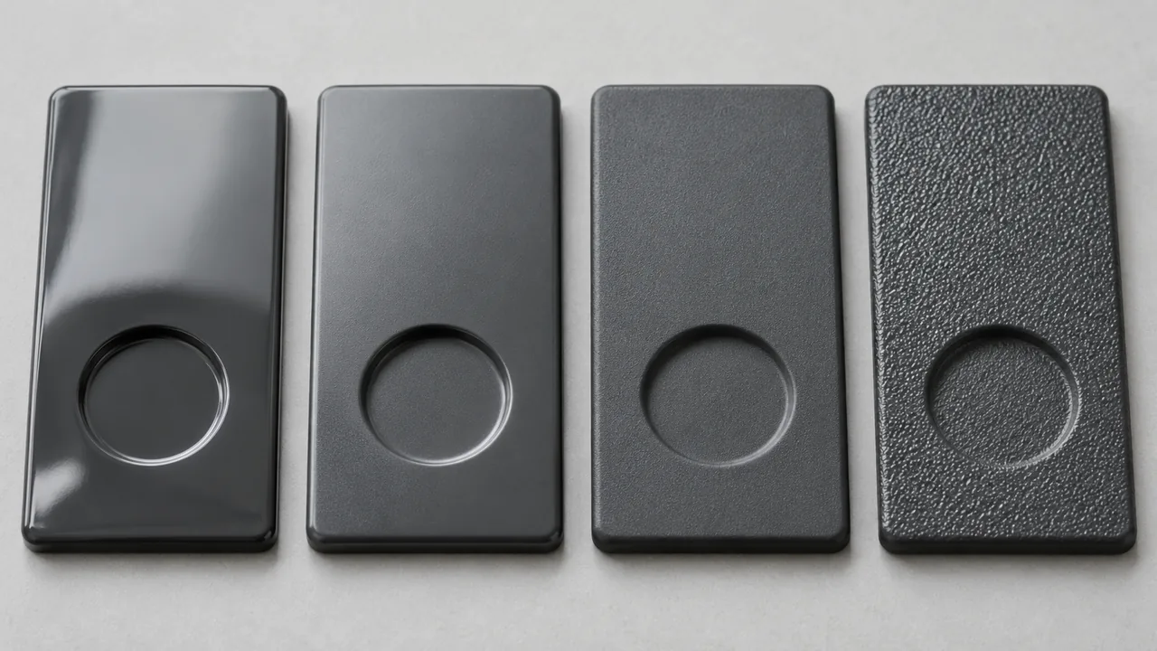
Molded appearance comes from the resin, cavity surface, tool texture, and processing conditions. Painting, printing, coating, or other secondary decoration are separate operations with their own specifications. We distinguish these routes during quotation so the required finish is included in the project scope.
For transparent or highly visible parts, agree on inspection lighting, viewing distance, reference samples, and acceptable variation. For functional parts, define sealing, fit, movement, or load requirements alongside appearance.
06 / Tooling to production
Approve the tool. Confirm the process.
Tooling development and molded-part approval are connected milestones. We coordinate sample feedback, necessary adjustments, and inspection evidence before releasing repeat production.
- ReviewConfirm drawings, material, demand, and acceptance requirements.
- BuildDevelop the mold around the approved design and tooling scope.
- TrialEvaluate samples, process behavior, dimensions, and appearance.
- ApproveResolve agreed actions and establish the approved sample baseline.
- ProduceRun the agreed production route with checks and traceability defined for the project.
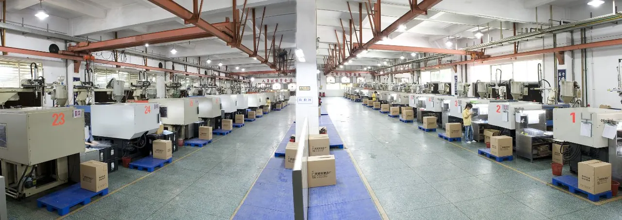
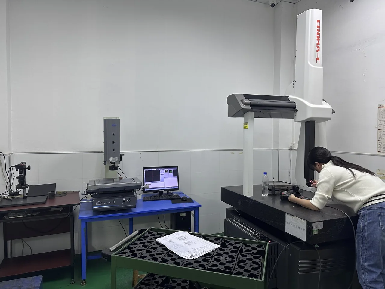
Our manufacturing base operates an ISO 9001 quality management system. Project inspection plans address relevant dimensions, visible surfaces, material identification, and functional checks; documentation requirements are confirmed with your team. Visit our facility and quality page for manufacturing context, or review our mold manufacturing services.
07 / Application context
Built around the assembly it belongs to
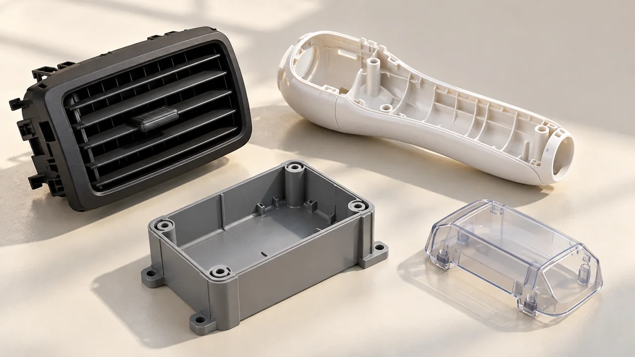
A housing, bracket, connector, or medical-device component brings its own assembly and service requirements. We review each drawing against those requirements rather than assuming that a sector name defines the specification.
Project questions
Injection molding FAQ
What information is needed for a molding quote?
Send a 3D model, dimensioned drawing, material or property requirements, expected quantities, and appearance and inspection criteria. Include assembly context and any secondary operations. We identify missing inputs during review.
Can you recommend a resin?
We can discuss candidates based on mechanical, thermal, chemical, appearance, and assembly requirements. The final grade and any required product validation need agreement before tooling and production approval.
Can you produce parts with an existing mold?
We can review an existing mold for transfer and production. Send the mold drawings, machine interface details, resin, maintenance history and approved samples. Compatibility, condition and any modifications are assessed before accepting the production route.
Do you support small batches and repeat production?
Yes. Share initial and annual quantities, the design stage and expected reorder pattern. Tooling investment, cavity count, setup and inspection requirements inform a practical batch size; the minimum quantity is confirmed for each project.
How are dimensions and inspection requirements agreed?
Mark critical dimensions, visible surfaces and functional requirements on the drawing. Tolerance feasibility depends on geometry, resin, tooling, process and measurement conditions. We agree inspection methods and documentation requirements before sample and production approval.
How quickly will I receive a quote and production schedule?
We aim to provide a quotation within 24 hours when complete inputs are available. Mold manufacturing, a detailed DFM review, material evaluation and the production schedule are confirmed separately for the project.
Start with the part
Send your drawing for a molding review
Share your CAD files, material requirements, quantities, and acceptance criteria. We will review the process route and quotation scope with your team. An NDA can be arranged when needed.
Request a quote