
Two injection units · One coordinated process
Two-Shot Injection Molding Services
Produce two-material components through a coordinated first shot, indexing stage, and second shot, with the interface and tool sequence engineered together.
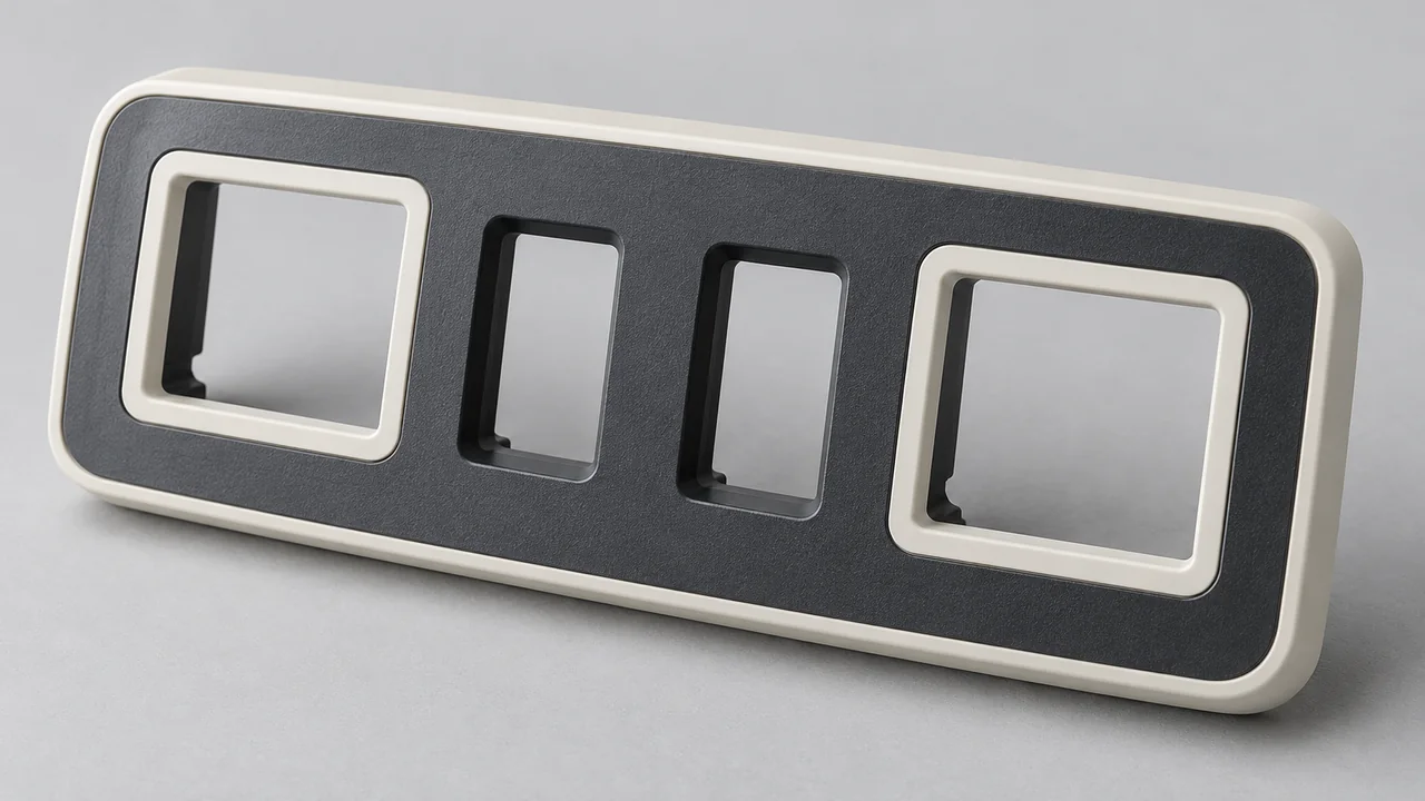
Two materials. A shared production route.
Make the interface part of the molding plan
Two-shot injection molding, also called 2K molding, forms a component using two injection stages. The first material establishes one region; the second material forms the complementary region within a coordinated tooling sequence.
Yiot Technology provides two-shot molding in-house using equipment with dual injection units. We assess both shot requirements and the mold architecture against your geometry, material pair, production demand, and acceptance criteria.
The process can combine colors, rigid and soft regions, or transparent and opaque features. Evaluate the coordinated cycle value against its tooling investment and expected production demand.
01 / Application features
Two materials with distinct roles
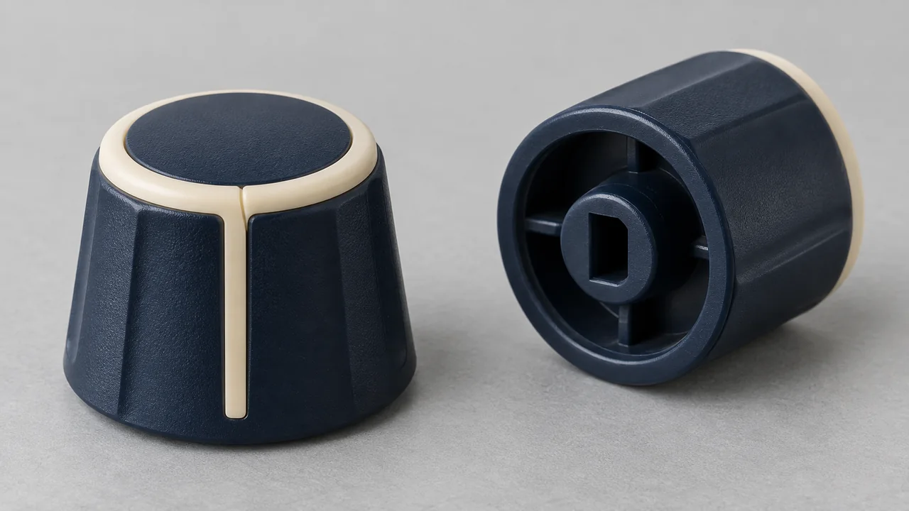
Multicolor controls
Different molded colors can define visible regions in a control component. Boundary quality, color matching, gate locations, and cosmetic criteria guide the design.
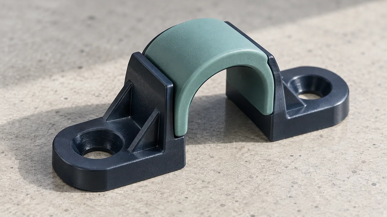
Hard-soft functions
A rigid structure can be combined with a flexible contact region. The material pair, retention geometry, and service conditions determine interface feasibility.
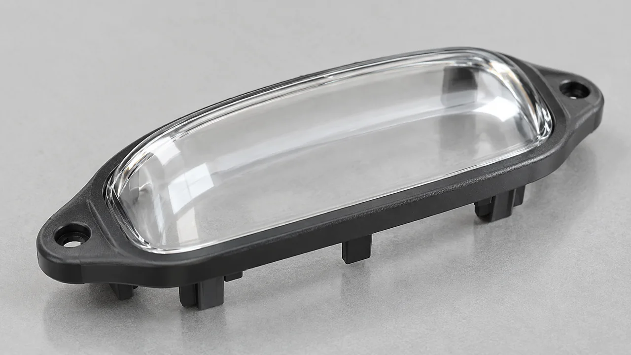
Clear & opaque features
Transparent regions can sit alongside opaque structures. Optical appearance, exposed edges, flow marks, and assembly requirements need specific acceptance criteria.
02 / The coordinated cycle
First shot. Index. Second shot. Eject.
The mold sequence keeps the first-shot component controlled while presenting it to the second cavity. The specific indexing or transfer arrangement is selected for the tool.
The first shot must fill, cool sufficiently, and remain in the intended position. During indexing, the component moves into the second molding position without losing the references needed for alignment. The second shot then forms against or around the first material before the completed component is released.
Two injection units allow the materials to be processed with their respective requirements. Their shot capacities, injection behavior, and compatibility with the tool must suit the project; the machine’s nominal clamping force is only one selection factor.
03 / Tooling priorities
Control both shots and the space between them
Two-shot tooling must support the first component, align the second cavity, manage two material flows, and release the finished part without damaging either region.
First-shot retention
Determine where the first component stays, how it is supported, and which surfaces remain accessible to the second shot.
Second-shot alignment
Review indexing references, fit between stations, and the features that establish the second material’s boundary.
Runners & gates
Consider each material’s fill path, visible vestiges, flow balance, and the position of weld lines relative to function.
Cooling
Evaluate cooling needs for both regions and the condition of the first material when the second shot arrives.
Ejection
Plan release forces and contact points so the completed component exits without distortion or surface damage.
Shrinkage
Review the dimensional interaction of the materials, including differential shrinkage and local stress around the interface.
04 / Interface engineering
A clean boundary needs a defined interface
The first-shot geometry and second-shot shut-offs determine where the materials meet. The design must consider retention, appearance, assembly loads, and any functional seal.
Compatible grades may develop adhesion under suitable molding conditions. Where the design requires it, mechanical capture can help retain the regions. Neither a two-shot machine nor a material family name establishes guaranteed bond performance; exact grades and trial verification remain essential.
Define boundary appearance, color, transparency, and visible tooling marks. For functional interfaces, agree on the relevant peel, pull, compression, sealing, or assembly test, including conditioning requirements.
We use DFM review to connect these requirements to wall thickness, draft, mold movement, and access. Detailed review scope and timing are agreed according to the project’s complexity.
05 / Process comparison
Two-shot or transfer overmolding?
| Consideration | Two-shot molding | Transfer overmolding |
|---|---|---|
| Sequence | Coordinated first and second shots with suitable indexing | Separately prepared substrate loaded for an additional molding operation |
| Handling | First-shot location maintained within the coordinated process | Transfer, storage, and loading need separate control |
| Investment | More involved tool sequence and dual-unit equipment requirements | Separate-stage tooling with substrate locating and support |
| Production fit | Evaluate repeat volume, cycle, tool complexity, and change expectations | Evaluate batch flexibility, loading, substrate supply, and total labor |
We review the complete cost and manufacturing picture rather than selecting by volume alone. Transfer overmolding may suit certain geometries or supply arrangements. Two-shot molding may suit a coordinated repeat-production route when the tooling and materials support it.
06 / Trials & repeat production
Approve both regions as one component
Trials check first-shot quality, indexing, second-shot fill, interface condition, dimensions, and release. A problem in one stage can affect the final assembly even when the other material region looks acceptable.
Approved samples establish the production baseline for material identification, boundary consistency, critical dimensions, and agreed interface tests. Assess grade or process changes against that baseline.
See our facility and quality approach →Project questions
Two-shot injection molding FAQ
Do you have two-shot molding equipment in-house?
Yes. Our manufacturing equipment includes dual injection units for two-shot molding. We confirm machine and tooling suitability against the two materials, shot sizes, and component geometry.
Is two-shot molding the same as overmolding?
The terms describe related approaches. Two-shot molding coordinates two injection stages within a suitable tool sequence; transfer overmolding loads a separately prepared substrate for the added material.
Can the two materials have different colors?
Yes, suitable grades and colors can be considered. Define color references, visible boundaries, and cosmetic acceptance so material selection and trials address the intended appearance.
Does the process guarantee a permanent bond?
No universal bond applies. Exact grades, interface geometry, processing, and service conditions matter. The required retention or function is verified against project-agreed criteria.
When is two-shot tooling worth considering?
Consider it when the geometry and materials support a coordinated cycle and the expected production case justifies the tooling investment. We compare handling, volume, cycle, flexibility, and validation needs.
What is needed to quote a two-shot part?
Send separate material regions in CAD, grade requirements, drawings, demand, and interface criteria. We aim to respond within 24 hours with complete inputs; full technical review timing is agreed separately.
Continue your review
Related molding services
Quote preparation
Send both material regions for review
Share the complete component and its intended function. We will assess the two-shot route, tooling requirements, and quotation scope. An NDA is available when needed.
Request a two-shot molding quote- 3D model with first- and second-material regions identified
- Dimensioned drawing and assembly context
- Exact material grades or performance requirements
- Colors, transparency, texture, and visible boundaries
- Annual volume and expected batch quantities
- Critical dimensions and interface acceptance tests