
In-house component manufacturing
CNC Machining Services for Metal & Plastic Parts
Produce custom metal and plastic components with in-house CNC machining. Define materials, critical dimensions, surface requirements and inspection criteria before production.
YIOT supports custom component projects from drawing review through machining and inspection. We review the features that affect manufacture and agree the requirements that determine part acceptance. Share the intended application and assembly context so the process plan reflects how the component will be used.
Request a CNC Quote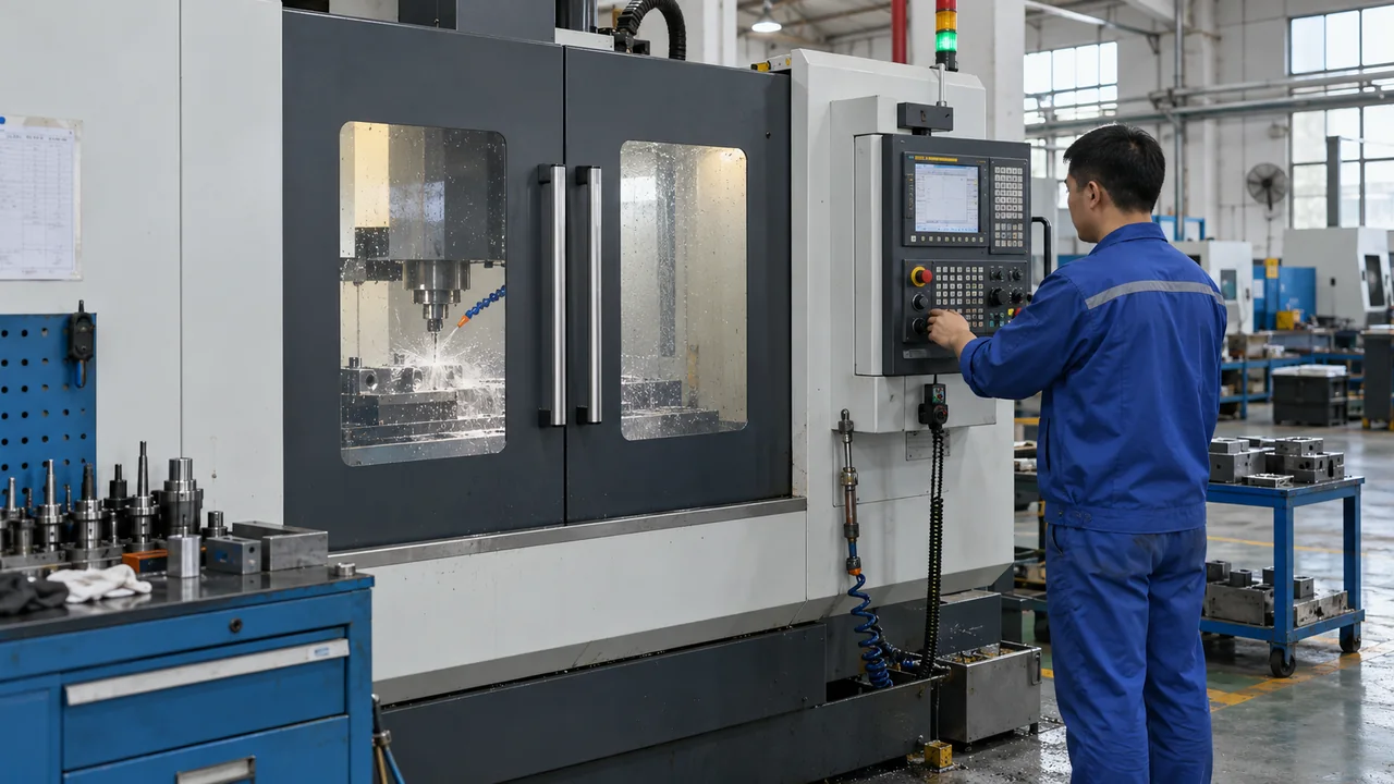
Parts for your application
Custom Parts, Not Only Mold Components
Our CNC capability supports metal and plastic parts as well as tooling-related work. Typical project discussions may involve housings, brackets, locating parts, covers or functional prototype components. A project begins with your geometry, chosen material and the role of each important feature.
Some components are defined by a drawing; others require an early design review to resolve interfaces or manufacturability. We can discuss those questions before machining starts. Quantity, revision status and whether parts need secondary operations all contribute to the quotation and manufacturing plan.
Include adjacent parts or an assembly view when a component’s purpose is difficult to understand from its model alone. This context helps distinguish a functional locating surface from a clearance feature and identifies where appearance or tool access matters. It also helps explain the consequences of a proposed design adjustment.
Specify the grade
Materials for Metal and Plastic Parts
Material families provide a starting point. We confirm the grade, supply form and application requirements for each project. Where material behavior affects fit or finish, the review should include operating conditions and the mating components.
Aluminum and brass
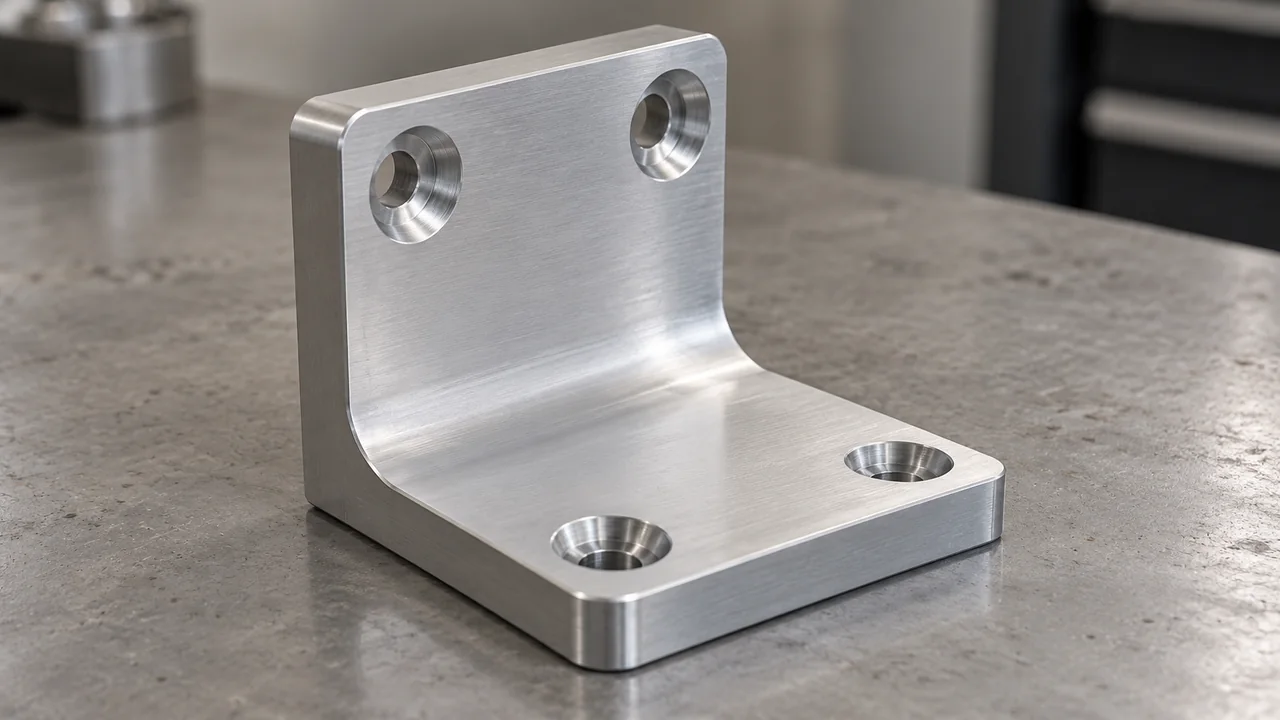
Aluminum may suit parts where weight and machinability matter. Brass may be considered for appropriate mechanical or connection applications. Specify the grade and any surface treatment so material selection and finishing can be reviewed together.
Stainless steel
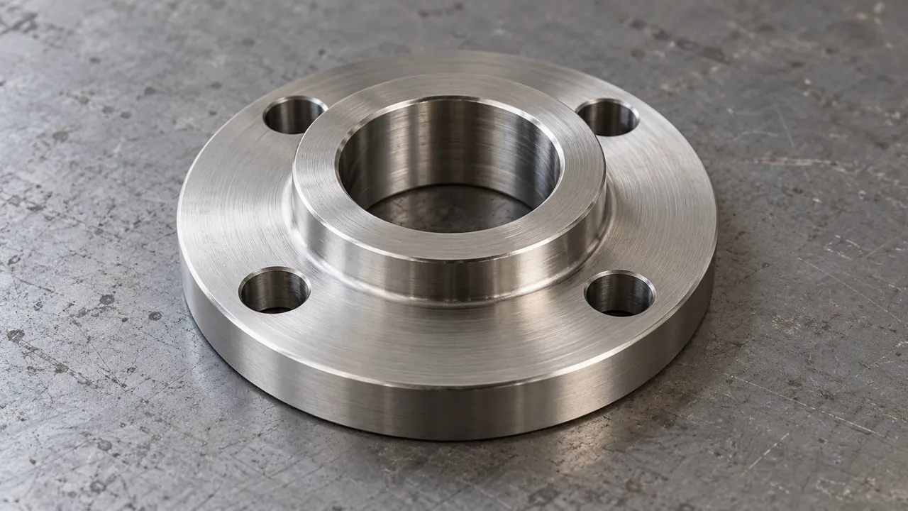
Stainless steel is a candidate when the application calls for the properties of a particular grade. Grade selection, feature geometry and surface expectations influence machining decisions. Avoid substituting one stainless grade for another without a documented review.
Engineering plastics
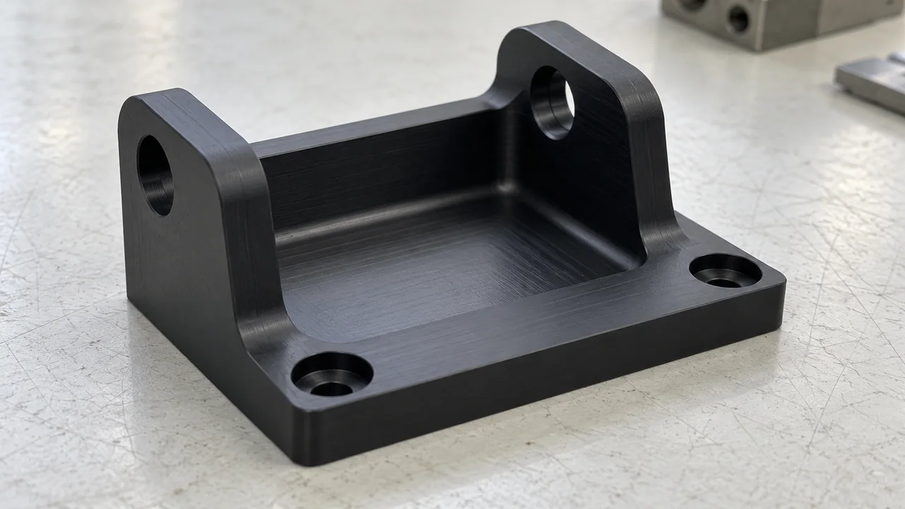
POM, PA, PC and ABS are candidate materials for suitable projects. Each has different stiffness, moisture response, temperature behavior and finishing limitations. Identify the required grade and clarify whether the component must represent a later molded product.
Make geometry manufacturable
Design Features That Affect Machining
Cutting tools need access to every machined surface. Internal corners retain a tool radius, and a deep cavity may restrict tool reach or chip removal. Specify which surfaces matter to assembly so we can discuss practical radii and access without changing the purpose of the part.
Thin walls and slender features need support during cutting and handling. Holes, blind features and threads should be clearly defined, including depth and the intended connection. Where a feature is difficult to manufacture, we can raise a design question for your approval before production.
The diagram shows common review points. It is a geometry explanation; the final cutter choice, setup and allowable variation depend on the actual drawing, material and inspection plan.
Measure from the right references
Datums, Fits and Critical Dimensions
Identify the surfaces that locate the component in its assembly. A hole position means more when it is related to the reference faces used by the mating part. Clear datums help connect drawing requirements, machining setups and the measurement method.
Tell us which dimensions are critical and explain the fit they control. A shaft, bore, mounting pattern or sealing interface may require different attention from an external clearance surface. General drawing requirements and specific feature requirements should be consistent and unambiguous.
Achievable part tolerance is assessed from the geometry, material, process and measurement method. Equipment specifications alone do not establish a finished component’s tolerance. We confirm agreed requirements during the project review and raise any unresolved drawing questions.
Plan the sequence
Workholding and Process Planning
The part needs to be held securely while the required surfaces remain accessible. Clamping locations, stock allowance and the order of operations affect how a component is produced. Multiple setups may be needed to reach features on different faces.
For flexible plastic parts or thin sections, support and clamping deserve particular attention. We review the geometry to plan suitable holding and processing, then connect that plan with the reference features used for inspection. Any proposed design adjustment is discussed before it becomes a manufacturing change.
Controlled drawings and revision identification help maintain consistency across the job. If your design changes after quotation, send the revised files and a change summary so material, process planning and acceptance requirements can be checked again.
Finish with a defined check
Surface Finish and Inspection
Describe the surfaces that are visible, functional or in contact with other parts. A cosmetic expectation should include a reference or approved sample where practical. Functional surface requirements belong on the drawing, with the features and measurement approach clearly identified.
Deburring, edge conditions and secondary finishing can affect fit and appearance. We review them alongside the material and application, rather than treating them as an unspecified final step. For related plastic finishing or assembly needs, visit finishing and assembly services.
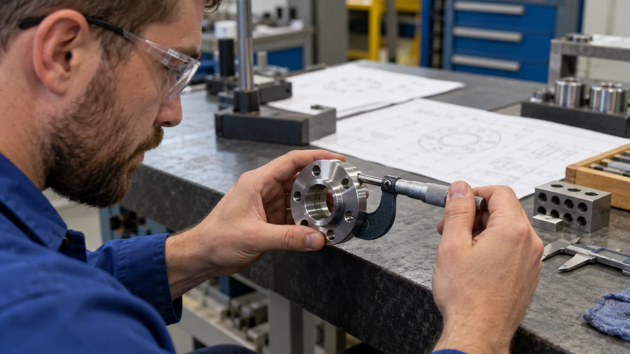
Inspection focuses on the agreed drawing and critical characteristics. Confirm the measurements or records needed for your project before production. Sample review can resolve appearance expectations and interface questions before a repeat order proceeds.
CNC Machining FAQ
What information is needed for a CNC quotation?
Send the CAD model, drawing, quantity, material grade and revision. Highlight critical dimensions, surface requirements, threads and inspection records needed for acceptance.
Which metals and plastics can you review?
Candidate families include aluminum, stainless steel, brass, POM, PA, PC and ABS. Suitability and grade availability are confirmed for the application and geometry during project review.
Can you quote prototypes and repeat quantities?
Yes. Share the initial quantity and expected repeat demand. Setup, material and inspection requirements are reviewed for the requested order rather than assumed from quantity alone.
What tolerance can you achieve?
Send your drawing requirements and identify the critical features. We assess them against material, geometry, setups and measurement method, then confirm the requirements we can support for that project. If the CAD model and drawing differ, we resolve the controlling information before production. Specifying the fit or function behind a tight requirement helps the review focus on the feature that matters.
Can you include finishing?
Tell us the required surface condition and application. Finishing compatibility, masking and its effect on important dimensions are reviewed before it is included in the manufacturing plan. Identify contact surfaces and areas where buildup, color variation or handling marks could affect acceptance. An agreed reference is useful when visual expectations are central to the order.
When will I receive a quotation and parts?
With complete inputs, a quotation is available within 24 hours. Manufacturing and validation timing is confirmed per project after reviewing material, quantity, features, finishing and inspection.
Bring the drawing into focus
Share Your Component Requirements
Send current files, grade, quantity and the features that matter most. Include your intended deadline and any assembly references. An NDA is available for confidential projects. We can also connect machining with DFM analysis, rapid prototyping, product applications and mold manufacturing.
Request a CNC Quote