
An automotive radar housing must locate sensitive electronics while keeping mounting, sealing, connector, and signal transmission requirements aligned. Its structural body and radar window need coordinated material and geometry decisions, supported by tooling and inspection that preserve the module’s critical assembly interfaces.
Automotive Radar Housing
Project Overview
| Application | Housing for an automotive radar module |
|---|---|
| Project context | Anonymous automotive application completed by YIOT |
| Engineering priorities | Mounting datums, enclosure fit, sealing interfaces, and RF compatibility |
| Recommended Configuration | Separate assessment of structural body and signal transmission window |
| YIOT capabilities | DFM, mold manufacturing, injection molding, CNC machining, and finishing |
Requirements & Engineering Challenges
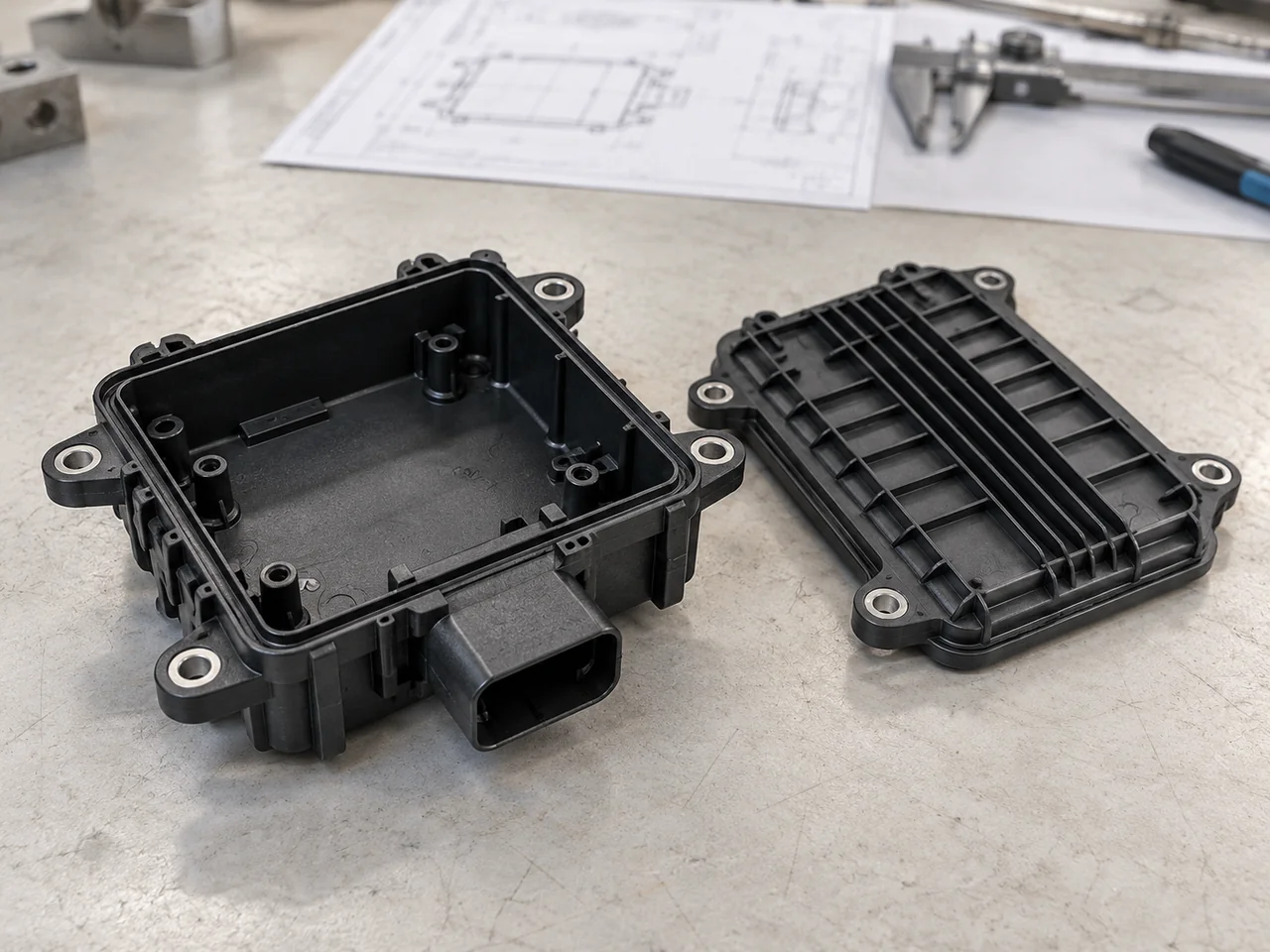
A radar module combines an electrical assembly with a mechanically exposed enclosure. Mounting ears establish its position in the vehicle, connector features locate the harness, and the cover joint protects internal components. These functions interact: distortion at a screw boss can change the cover gap, while a local rib or coating in the antenna region can affect the transmission path. The engineering task therefore begins with an interface map rather than an isolated exterior model.
The most important distinction is between a structural housing and a radar transmission window. A material suitable for a stiff enclosure is not automatically suitable across the antenna aperture. The customer’s radar team must define operating frequency, permitted attenuation, dielectric requirements, window thickness, and environmental test conditions. YIOT can support the geometry and manufacturing review against those inputs; RF performance remains an assembly validation requirement.
Engineering & Tooling Approach
Separate material selection by function
Recommended Configuration: assess an automotive engineering thermoplastic, such as a suitable PBT grade, for the structural body. Reinforcement, hydrolysis resistance, and flame behavior are grade-dependent choices. For any surface crossed by the radar signal, use a material and thickness released by the customer’s RF design team. Pigments, fillers, coatings, and moisture conditioning belong in that approval because a change in formulation can alter behavior even when the resin family stays the same.
The material specification should identify the full grade, color, permitted additives, and regrind policy. A resin substitution requires an engineering review rather than a purchasing-only decision. For prototypes, a machined enclosure can help assess package space and fastener access, but it does not reproduce molded fiber orientation or establish the RF behavior of production parts.
Control datums before cosmetic surfaces
The drawing should establish functional datums at the mounting and electronics interfaces. Boss centers, connector alignment, and the cover seating plane can then be inspected from a consistent reference system. Thick intersections between ribs and bosses should be cored or redistributed where possible. This addresses localized shrinkage without removing the load path needed for installation torque.
A seal groove requires its own review of corner radii, groove continuity, joint compression, and assembly stops. The parting line should avoid crossing a critical sealing land where practical. If it must cross that region, the tool design and inspection plan must explicitly control mismatch and flash. Seal performance depends on the complete joint, including the selected gasket and fastening sequence.
Design the tool around predictable release
Gate placement should be evaluated against the housing’s longest flow paths, connector corners, and mounting features. Flow-front meeting points near a loaded ear deserve attention before steel is cut. Venting must allow air to escape from terminal ribs and deep pockets without creating a leakage path on the finished joint. Mold filling analysis can inform these decisions when geometry or material behavior warrants it.
Recommended Configuration: use serviceable inserts around connector openings, narrow seal details, and wear-prone shutoffs. A hardened tool steel such as H13 can be considered for abrasive reinforced compounds; the final selection depends on resin, finish, expected production volume, and maintenance requirements. Cooling and ejection should support the joint plane evenly so that release forces do not twist the housing.
Define the RF and mechanical change boundary
The manufacturing release should identify protected features in the antenna region. Texturing, marking, gate relocation, and decorative finishing must be reviewed before being added there. Outside that region, controlled texture can make handling marks less visible, provided the required draft supports release. Any CNC operation after molding needs a fixture that references the same functional datums used for inspection.
A revision record should connect geometry changes with the relevant approval owner. A minor-looking wall change may require both mold adjustment and RF review. Keeping those decisions together makes a subsequent production order easier to reproduce and prevents an appearance revision from silently changing a functional surface.
- 1. RF window
Assess the signal window material and section separately from the structural body. - 2. Seal path
Review the continuous joint, gasket seating and assembly compression. - 3. Mounting datum
Reference mounting geometry and inspection to the released datum system. - 4. Connector
Coordinate the connector opening, mating alignment and serviceable tooling details.
Manufacturing & Validation
The manufacturing plan covers resin identification, drying according to the selected supplier’s instructions, mold temperature control, and a stable molding process. Trial samples should be identified by tool revision and cavity so that dimensional observations can be traced back to their source. Cosmetic checks should distinguish gate vestige, weld lines, flash, and handling damage instead of grouping all visible differences into one acceptance category.
Validation should check mounting location, cover fit, connector mating, and sealing-land geometry against released requirements. Where specified, customer-approved laboratories or the system owner conduct environmental, vibration, ingress, and RF evaluations using representative assemblies. A dimensional report on an empty housing cannot replace those tests. Acceptance samples and inspection methods should be agreed before production release.

Deliverables & Project Outcome
YIOT can support radar housing programs from DFM through tooling and molded-part supply. Agreed deliverables can include manufacturing recommendations, an approved mold design, development samples, production components, and inspection records. Tool ownership, spare inserts, packaging, and document handover should be included in the quotation scope so the manufacturing arrangement is clear before release.
Acceptance should connect the housing’s mounting, connector, and cover interfaces with the approved module-level checks. The release package should identify the resin grade, tool revision, protected RF features, and relevant assembly configuration. These records provide a basis for subsequent production orders, while RF and environmental performance are established through the specified validation program.
Technical reference: BASF’s Ultradur PBT portfolio identifies dimensional stability and low water absorption among its material characteristics. These support initial enclosure-body screening; surfaces in the radar transmission path require separate grade-specific RF assessment and module validation.
Related Capabilities
Discuss Your Project
Send the housing and cover models, datum drawing, antenna keep-out information, material requirements, annual quantity, and validation scope. YIOT can review the manufacturing route and identify the inputs needed for a useful tooling quotation.
An NDA is available. Request a quote or email gerry.li@aiyiot.com. YIOT provides a quotation within 24 hours after receiving complete project information. The DFM review timeline is assessed separately according to project scope.