
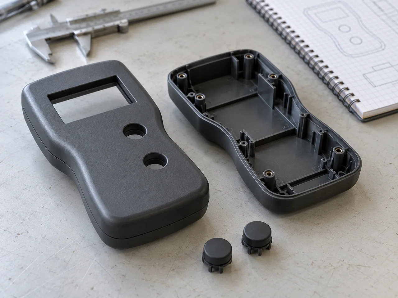
An electronic controller housing must locate the circuit board, align connectors, and close consistently around the internal assembly. Resin selection, screw-boss geometry, joint design, and finish requirements shape the tooling approach, while functional datums connect molded-part inspection with practical assembly checks.
Electronic Controller Housing
Project Overview
| Application | Molded enclosure for an electronic controller |
|---|---|
| Project context | Anonymous electronics application completed by YIOT |
| Engineering priorities | PCB location, connector fit, enclosure joint, and cosmetic consistency |
| Recommended Configuration | PC/ABS or another grade selected against the product requirements |
| YIOT capabilities | DFM, mold manufacturing, molding, CNC machining, and finishing |
Requirements & Engineering Challenges
The controller housing must preserve relationships between features that may be designed by different teams. The circuit board establishes connector location, the external product establishes mounting space, and the industrial design defines visible surfaces. A mismatch between those references can produce an enclosure that measures correctly in isolation but loads the board or misaligns a connector during assembly. The first engineering step is to agree which interfaces locate the assembly and which provide clearance.
Heat, electrical insulation, chemical exposure, and installation conditions influence the material and joint strategy. Ventilation openings, if required, must be considered alongside ingress protection and finger access requirements. A closed enclosure can create a different thermal condition from an open bench prototype. Neither the resin’s heat rating nor a successful fit check substitutes for evaluation of the operating controller in its intended installation.
Engineering & Tooling Approach
Choose a resin and finish as one system
Recommended Configuration: assess PC/ABS for a housing requiring a balance of impact behavior, dimensional control, and appearance. Other materials may be preferable where temperature, chemical exposure, stiffness, or electrical requirements dictate. The final specification should identify a full resin grade and color rather than use a broad family name as the entire purchasing requirement.
A painted, printed, textured, or plated surface adds manufacturing constraints. Finishing chemistry can affect stressed polymer regions, and coating thickness can change tight fits. The DFM review should identify masked surfaces, bonding lands, connector interfaces, and electrical contacts that must remain free of finish. A molded texture can be evaluated before adding a secondary coating if it meets the product’s appearance needs.
Locate the board without overconstraining it
Board supports should provide a clear seating plane and controlled lateral location. Multiple rigid locating features can create an assembly conflict when tolerances accumulate. Clearance at secondary supports allows the board to sit without being forced into shape. Fastener access, driver angle, cable bend space, and rework needs should be reviewed with representative hardware rather than judged from an exterior rendering.
Screw bosses need a defined fastening system. Self-tapping screws, thread-forming screws, and metal inserts impose different pilot geometry and local load paths. Coring the boss and connecting it with appropriately placed ribs can avoid heavy sections behind the cosmetic face. The tightening method and assembly torque must be established by the selected screw or insert system and checked on representative molded parts.
Make connector openings serviceable in the mold
Connector apertures often include small shoulders, narrow shutoffs, and local undercuts. The tool design should examine whether these can be formed in the main draw or require slides or lifters. A replaceable insert around an evolving connector interface can make future changes more practical, but its split line must not create unacceptable flash in the mating region.
Gate placement should support complete filling around openings without placing an objectionable vestige on a visible face. Weld lines near bosses and snap features deserve an engineering review because local appearance and strength can both matter. Venting around the final fill regions and adequate draft on textured walls should be resolved before the exterior finish is approved.
Manage the cover joint and tooling release
A tongue-and-groove joint can guide assembly, but its clearance must account for molding variation and any finishing thickness. Snap-fit retention should be reviewed for assembly deflection, release access, and repeated service if the controller is repairable. For a sealed design, hard stops and gasket compression need to be considered together rather than relying on fastener torque alone to control the joint.
Recommended Configuration: use production tooling with serviceable inserts at connector apertures, fastener details, and frequently revised markings. P20-type prehardened steel or a hardened alternative can be considered according to production demand, resin, finish, and tool maintenance expectations. Ejector placement should support internal structures and keep witness marks away from board seating and sealing surfaces.
- 1. Joint land
Control seating and release details around the upper and lower housing joint. - 2. Screw boss
Core the fastening feature and review tightening loads with the specified hardware. - 3. Board support
Locate the board from defined supports without overconstraining the assembly. - 4. Connector opening
Reference the opening to board location and review mating clearance.
Manufacturing & Validation
Molding preparation should follow the resin supplier’s grade-specific drying and processing guidance. Trial review should include both the individual housing parts and an assembled unit. A visible surface can look acceptable while its mating edge has distortion, so appearance approval and dimensional approval should remain distinct checks. Cavity identification and revision records help connect each sample to its manufacturing configuration.
The inspection plan can cover board standoff height, connector position, mounting datums, cover gap, fastener engagement, and cosmetic criteria. Assembly checks should look for board strain, pinching of wires, connector interference, and access to service items. Thermal, dielectric, EMC, flammability, or ingress evaluations are included only when specified and performed at the appropriate product level. A plastic enclosure by itself does not establish EMC compliance.

Deliverables & Project Outcome
YIOT can coordinate controller-housing DFM, mold manufacture, molding, and agreed finishing. Deliverables can include development samples, production parts, and inspection documentation referenced to the released interface drawing. Any assembly fixture or CNC operation should be included where the manufacturing process requires it, with the responsible party identified for board, connector, seal, and fastener supply.
The acceptance scope should connect the molded components to the intended controller assembly: correct interface geometry, approved visual surfaces, and defined fit and functional checks. Accepted samples should identify the resin, finish, tooling revision, and mating hardware. Thermal and compliance conclusions then follow the product validation plan using the specified electronic package and operating conditions.
Technical reference: Covestro’s Bayblend portfolio includes PC/ABS families and grade-specific flame-retardant options. Portfolio descriptions support material screening; the selected grade, color, minimum thickness, and end-product requirements still need individual review.
Related Capabilities
Discuss Your Project
Send the enclosure and lid models, board outline, connector data, mounting drawing, cosmetic requirements, material specification, and expected quantity. If a physical assembly is available, its mating hardware can help YIOT identify tolerance and access concerns early.
An NDA is available. Request a quote or email gerry.li@aiyiot.com. YIOT provides a quotation within 24 hours after receiving complete project information. The DFM review timeline is assessed separately according to project scope.