
Home energy storage enclosures combine broad visible covers with fastening, cable, and service interfaces. Molded components need controlled panel shape and joint geometry, with material requirements and manufacturing methods coordinated around the structural chassis, electrical layout, installation conditions, and maintenance needs.
Home Energy Storage Enclosures
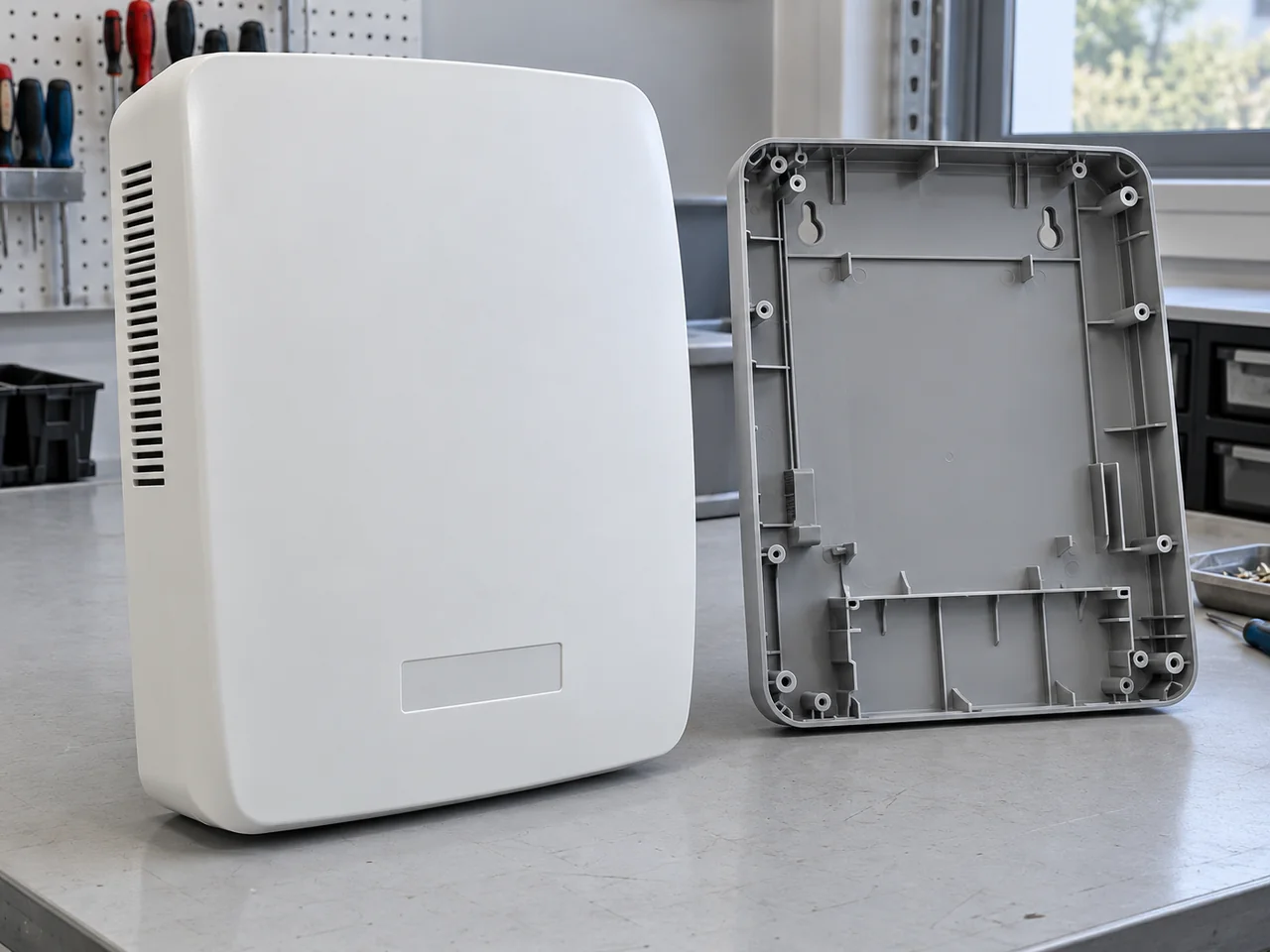
Project Overview
| Application | Molded enclosure components for home energy storage equipment |
|---|---|
| Project context | Anonymous energy-product application completed by YIOT |
| Engineering priorities | Panel fit, fastening, service access, and material requirements |
| Recommended Configuration | Grade-specific polymer coordinated with the complete enclosure architecture |
| YIOT capabilities | DFM, tooling, injection molding, CNC machining, finishing, and assembly |
Requirements & Engineering Challenges
A home energy storage enclosure may combine a structural chassis, molded outer covers, access panels, display interfaces, and cable-entry components. These parts have different responsibilities. A cosmetic polymer cover should not be assumed to carry battery weight or provide a fire barrier. The project definition must identify the structural load path and the protective role assigned to each molded component.
The product owner’s electrical and system design establish service clearances, ventilation, cable routing, isolation, environmental exposure, and applicable market requirements. Those inputs shape the part geometry and material specification. A wide cover also presents a manufacturing challenge: local shrinkage, uneven cooling, or assembly loads can affect a seam over a long distance. The tooling review must consider the entire joint rather than only isolated dimensions.
Engineering & Tooling Approach
Define the enclosure architecture before material choice
Recommended Configuration: evaluate an engineering polymer grade against the cover’s specified temperature, impact, electrical, chemical, and appearance requirements. Flame-retardant PC/ABS, polycarbonate, or another suitable material may enter screening, but the final choice must follow the component’s role and the system requirements. Grade, color, minimum section, and any permitted recycled content need to be released together.
Outdoor or semi-exposed installations can add UV, humidity, condensation, and cleaning-agent requirements. These should be stated explicitly rather than implied by the phrase home energy storage. Material documentation and traceability should support the customer’s qualification process. No substitution should be approved solely because another resin has a similar nominal flammability classification.
Control broad panels and long joints
Large visible surfaces benefit from consistent wall sections and deliberate transitions around ribs, bosses, and display openings. Local heavy sections can create sink or distort adjacent seams. Rib placement should reinforce the required structure without producing a repeated pattern on the outer face. The design should distinguish features that locate the cover from features that simply support it.
An inspection fixture must reference the intended installation datums. Pulling a panel flat with excessive clamping can conceal the condition the customer sees during assembly. Free-state profile and installed gap should therefore be defined separately. If the cover joins a metal chassis, the tolerance review should include both manufacturing processes and their different thermal expansion behavior.
Make fastening and service access explicit
Fastener locations need access for the specified assembly tools and a suitable load path into the chassis or mating component. Repeatedly serviced areas may require a different fastening strategy from a cover intended to remain closed. Metal inserts can be considered where the load and service requirements justify them, but their retention and local stress effects require a separate interface review.
Cable entries, access doors, and display windows should be coordinated with the system layout. Sharp edges, uncontrolled flash, or a moving panel must not interfere with the specified harness routing. Where a gasket is required, groove geometry, compression stops, fastener spacing, and the complete seal path should be reviewed together. No ingress rating can be assigned from a groove design alone.
Plan the mold and secondary operations together
A broad enclosure component may need more than one gate, depending on geometry, resin, and machine selection. Gate strategy should be assessed against weld lines at mounting features, visible flow marks, pressure demand, and trimming access. Mold filling and warpage analysis can support the decision where the size or flow path makes trial-and-error changes costly.
Recommended Configuration: use production tooling with cooling arranged around the major panel regions and serviceable inserts at cable and fastening details. Tool steel and hot-runner selection depend on the released resin, finish, shot size, and production forecast. CNC trimming, machining, or finishing can be included where justified, with fixtures referenced to functional datums. Secondary work should not compensate for an undefined assembly interface.
- 1. Panel ribs / vents
Review panel sections, reinforcement and ventilation features against system requirements. - 2. Mounting datum
Locate the molded cover from the assigned frame interfaces and fastening points. - 3. Service access
Coordinate the removable access area and tool approach with the product layout. - 4. Joint / cable zone
Review the cover joint, cable entry and fastening access as a coordinated interface.
Manufacturing & Validation
The manufacturing plan should connect resin lot identification, grade-specific material handling, process settings, cavity identity, and part revision. Broad surfaces need a visual standard that separates allowable texture variation from sink, flow marks, contamination, or damage. Packaging and handling should support the cosmetic requirements because panel edges and corners can be vulnerable after molding.
Dimensional and assembly review can include panel profile, chassis fit, joint gaps, insert location, fastening access, cable-interface geometry, and service-panel operation. Environmental, mechanical, electrical, ingress, and battery-system evaluations must follow the product owner’s specified plan. A component inspection report is useful evidence for part conformity, but it cannot demonstrate thermal-runaway containment or certify the complete energy storage system.
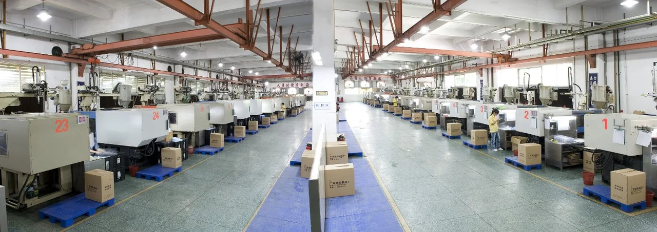
Deliverables & Project Outcome
YIOT can support enclosure-component DFM, tooling, molding, and agreed CNC or finishing operations. The deliverable scope can include sample covers and interface parts, production components, and inspection documentation. Metal parts, seals, hardware, and assembly operations should be assigned explicitly in the supply agreement, including responsibility for the representative chassis used during fit approval.
Acceptance should be based on the released component requirements and agreed checks with the complete enclosure architecture. Approved panel profiles, joint gaps, fastening interfaces, and service clearances provide a practical basis for production inspection. These component records support the product owner’s system-level qualification; fire protection, battery safety, and ingress performance require the corresponding complete-system evaluations.
Technical reference: UL Solutions’ plastics combustion-test guidance explains material flammability evaluation and thickness dependence. Such material data is only one input to enclosure design; it does not establish battery-system safety, fire containment, or end-product certification.
Related Capabilities
Discuss Your Project
Share the enclosure and chassis models, component responsibilities, material and finish requirements, service environment, forecast quantity, and validation scope. YIOT can review moldability and assembly interfaces without separating the cover from the system it must fit.
An NDA is available. Request a quote or email gerry.li@aiyiot.com. YIOT provides a quotation within 24 hours after receiving complete project information. The DFM review timeline is assessed separately according to project scope.