
An insert-molded instrument housing combines polymer geometry with metal fastening or locating features. Insert position, retention details, thread protection, and melt flow need to be engineered together so that molding preserves the functional interfaces required by the instrument and its mating hardware.
Insert-Molded Instrument Housing
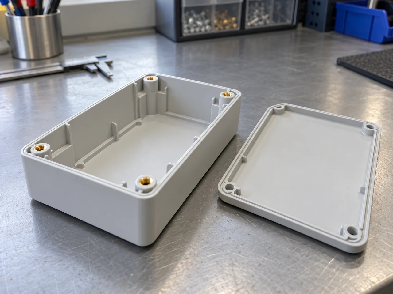
Project Overview
| Application | Instrument housing with integrated metal inserts |
|---|---|
| Project context | Anonymous instrument application completed by YIOT |
| Engineering priorities | Insert position, retention, thread protection, and housing fit |
| Recommended Configuration | Purpose-designed metal inserts and a grade-specific molding polymer |
| YIOT capabilities | In-house insert molding, tooling, DFM, CNC machining, and finishing |
Requirements & Engineering Challenges
An instrument housing may need threaded connections, locating bushings, or metal mounting features that remain aligned with a sensor, display, or internal assembly. Insert molding places those features in the mold before plastic is injected around them. The resulting component depends on two manufactured parts and their interaction: the incoming insert has its own tolerances, and the molded housing adds shrinkage, cooling behavior, and assembly loads.
The critical questions are therefore broader than whether an insert can be enclosed in plastic. It must be loaded in the correct orientation, supported against injection pressure, kept clear of polymer where mating is required, and retained under the specified service load. The housing must also avoid local distortion or cracking around the metal. These interfaces need explicit drawing and acceptance requirements.
Engineering & Tooling Approach
Design the insert for molding and service
Recommended Configuration: use an insert with a defined locating shoulder and external retention geometry suitable for the selected polymer. Knurls, grooves, flats, or undercuts can provide mechanical engagement, but their shape should allow melt to fill without trapping air. A smooth metal cylinder should not be assumed to develop adequate retention simply because it is surrounded by a molded boss.
The insert material and finish must suit the operating environment and any contact with dissimilar metals. Thread form, plating, burr limits, and cleanliness belong in the incoming component specification. If a threaded insert is used, its working thread should remain accessible after molding and its orientation should be distinguishable during loading. A prototype insert can be CNC machined for development before a production supply method is finalized.
Create repeatable location inside the tool
The tool should locate each insert against stable reference features rather than an uncontrolled rough surface. A pin, shoulder, nest, or keyed pocket can establish position and prevent reversal. Support must resist the direction of pressure applied by the advancing melt. Where an insert has a long unsupported span, the design review should assess deflection or movement during filling.
Thread protection and shutoff need particular attention. The tool must keep resin out of the functional thread without crushing an oversized insert or leaving flash around an undersized one. Incoming insert tolerances and mold clearances therefore have to be reviewed together. Replaceable locating pins and wear inserts can simplify maintenance at these contact surfaces.
Control polymer flow around the metal
Gate location should promote balanced filling around the insert and avoid a direct jet that dislodges it. The flow may split around metal and meet again nearby, creating a weld line in a loaded region. Venting, gate strategy, local section thickness, and material choice should be considered together before that location is accepted. Filling analysis can be useful where the geometry has several inserts or long flow paths.
Metal removes heat from the melt differently from the surrounding mold cavity, and polymer shrinkage around the insert can create residual stress. The boss should have gradual transitions and enough supporting structure without becoming an unnecessarily thick mass. Insert preheating is a process option only after evaluating the material pair, loading method, handling safety, and dimensional requirements; it is not a universal requirement.
Choose the material and loading route together
Recommended Configuration: assess an engineering polymer such as PBT, polyamide, or PC/ABS against stiffness, temperature, moisture, chemical, and electrical requirements. The material choice influences shrinkage around the insert and the load carried by the boss. A supplier data sheet is a screening tool; retention needs testing in the actual molded geometry.
Manual loading can suit development or a limited insert count. A larger program may justify dedicated loading nests, presence checks, or automated handling, subject to a separate process review. The production sequence should define how inserts are stored, cleaned if necessary, loaded, verified, and removed after molding. Missing-insert prevention should be matched to the application’s risk and production arrangement rather than described as an unspecified automation promise.
- 1. Insert shoulder
Provide a defined metal seating feature and review insert loading orientation. - 2. Thread shutoff
Use a mold locating pin and controlled shutoff to protect the threaded interface. - 3. Retention relief
Review knurling and polymer capture geometry together with local wall sections. - 4. Locating support
Support the insert in the tool so injection pressure does not shift its location.
Manufacturing & Validation
The molding process begins with identified insert and resin lots. Trial records should link insert dimensions, tool revision, molding conditions, and sample identity so that retention or positional issues can be investigated. Visual checks should distinguish resin flash, exposed retention features, voids visible at an interface, damaged plating, and deformation of a functional thread. A clean external appearance alone does not demonstrate internal engagement.
Dimensional inspection can establish insert position relative to housing datums and the alignment of mating interfaces. Thread gauges, torque testing, pull-out testing, or sectioning may be appropriate where the customer defines the method and acceptance limits. Thermal cycling or environmental exposure can be included when service conditions justify it. Destructive samples and their conditioning state should be planned before production release, with the sampling frequency agreed in the quality plan.
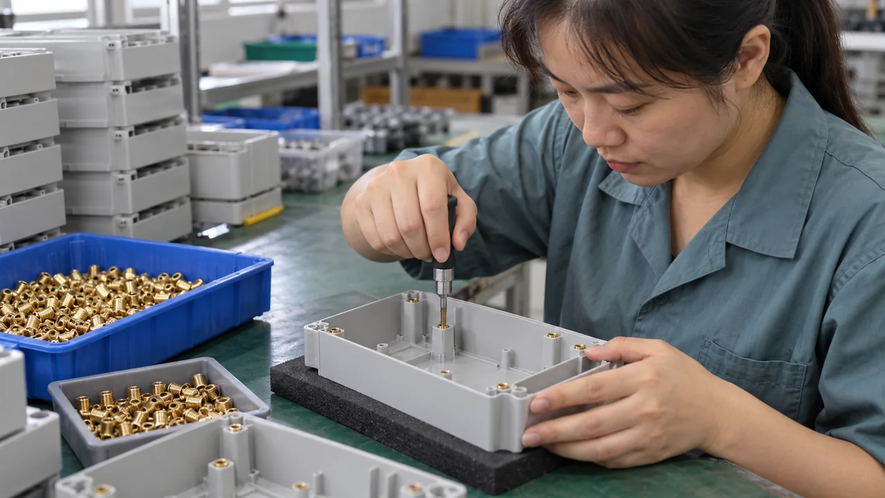
Deliverables & Project Outcome
YIOT provides insert molding in-house, supported by DFM, mold manufacture, and CNC machining capabilities. Agreed deliverables can include an insert-interface review, tooling, molded development samples, production housings, and inspection records. Insert procurement responsibility, incoming inspection, loading fixtures, and spare locating features should be stated in the project scope alongside the molded-part supply requirements.
Acceptance should establish the relationship between the metal features and housing datums, together with the specified retention and assembly checks. Approved samples and records should identify insert geometry, material, finish, molding revision, and test conditioning where relevant. These details support consistent repeat manufacture and provide a defined basis for evaluating future insert or housing changes.
Technical reference: BASF’s Ultradur PBT material information provides a starting point for evaluating dimensional and electrical characteristics. Insert retention, local stresses, and molding conditions must be engineered for the actual polymer grade and metal geometry.
Related Capabilities
Discuss Your Project
Provide the housing model, insert drawing, insert material and finish, mating hardware, required loads, expected quantity, and inspection requirements. YIOT can assess the insert loading and tooling arrangement alongside the molded component.
An NDA is available. Request a quote or email gerry.li@aiyiot.com. YIOT provides a quotation within 24 hours after receiving complete project information. The DFM review timeline is assessed separately according to project scope.