Retractable leash components must keep a loaded mechanism aligned inside a comfortable hand-held enclosure. Housing geometry, spool clearance, brake engagement, and grip attachment each need a defined manufacturing approach, supported by assembly checks that reflect how the complete product will be used.
Retractable Leash Components
Project Overview
| Application | Molded components for a retractable leash assembly |
|---|---|
| Project context | Anonymous consumer-product application completed by YIOT |
| Engineering priorities | Mechanism fit, retention, grip, and assembly repeatability |
| Recommended Configuration | Separate material decisions for housing, sliding parts, and soft grip |
| YIOT capabilities | Injection molding, tooling, insert molding, overmolding, and two-shot molding |
Requirements & Engineering Challenges
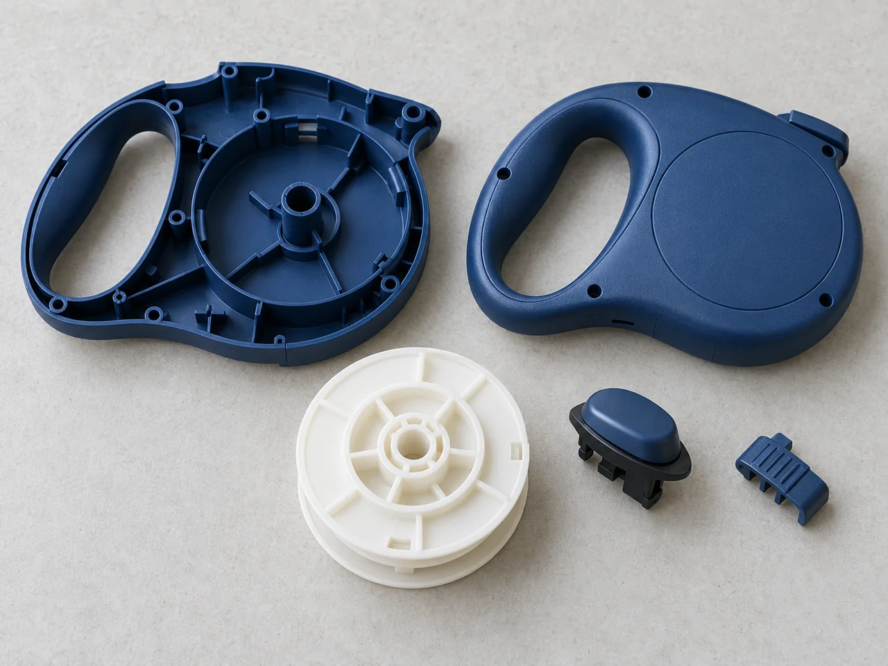
The enclosure of a retractable leash is also a structural and ergonomic component. It supports the spool axis, positions the brake control, contains the spring assembly, and transfers loads through the handle. The molded parts must fit without rubbing on rotating components or preventing full brake engagement. A visually aligned seam is useful, but it cannot be the sole measure of assembly quality when an internal mechanism carries the working load.
The product owner must define intended use, rated load, misuse conditions, cycle requirements, and applicable market requirements. Molded-part suppliers need those inputs to understand which bosses, stops, and interfaces are critical. Springs, webbing, cord, fasteners, and hooks also affect the final system. A housing material data sheet cannot establish that the complete leash is safe for a particular animal size or pulling force.
Engineering & Tooling Approach
Assign materials by mechanical role
Recommended Configuration: assess an impact-resistant housing polymer against the installation loads, drop exposure, and finish requirements. Evaluate a suitable low-friction engineering polymer for selected moving parts only after considering the actual mating material, lubrication strategy, temperature, and wear conditions. POM is one candidate for sliding components; it is not automatically the right material for every spool, latch, or brake feature.
A soft grip introduces a separate material decision. The selected TPE must be compatible with the rigid substrate if chemical adhesion is required. Mechanical retention can supplement that attachment where the design allows. Grip texture and hardness should be evaluated with the user’s hand positions, moisture exposure, and cleaning requirements rather than chosen from an appearance sample alone.
Protect the spool and braking datums
The spool-support features in the two housing halves should reference a consistent datum strategy. Uneven wall shrinkage or an assembly seam that pulls the halves sideways can change axle alignment and running clearance. Bosses should support the assembly loads without leaving heavy sections beneath a visible face. Local rib layout needs to reinforce the load path while maintaining predictable molding sections.
The brake button and its guide surfaces require enough clearance for reliable movement across the expected manufacturing and environmental range. Sharp parting-line flash in a sliding channel can cause sticking. The tool design should therefore place splits and ejector witness marks away from sensitive contact surfaces where practical. Critical stops need a clear load path into the housing, not only a convenient location in the model.
Develop the grip boundary for manufacture
A two-material handle should include a deliberate termination for the soft layer. Thin feather edges can be difficult to fill and vulnerable to peeling. A defined step, groove, or mechanical interlock can give the material a more controllable boundary, subject to the chosen TPE and substrate. The soft material should not flash into the spool cavity or onto mating features.
YIOT’s in-house overmolding and two-shot capabilities allow the manufacturing route to be reviewed alongside geometry. Insert overmolding may suit a staged process; two-shot molding may suit a program that justifies dedicated tooling and transfer arrangements. Recommended Configuration: choose between these routes from the material pair, grip coverage, forecast quantity, and handling needs. The route itself does not guarantee adhesion.
Keep the tooling maintainable
Gate placement should consider long handle sections, enclosed corners, and weld lines at loaded features. Venting is particularly relevant near the ends of narrow brake guides and grip cavities. Draft and texture should be coordinated so that the housing releases without scuffing and the soft layer is not stretched excessively during ejection.
Recommended Configuration: use replaceable inserts for brake guides, axle-support features, and the overmold shutoff. Family molding can be assessed for smaller components, but different projected areas and fill behavior may make separate tools more controllable. Steel, cavity count, runner design, and cooling should be selected together from production needs rather than inferred from the product’s compact size.
- 1. Soft grip
Define the grip material boundary and its attachment to the structural housing. - 2. Brake button
Coordinate button travel and contact interfaces with the released braking mechanism. - 3. Axle alignment
Maintain a common axis through the housing supports and spool assembly. - 4. Spool clearance
Review running and assembly clearances with representative spool components.
Manufacturing & Validation
Trial review should include a representative assembled mechanism. A spool that turns freely by hand before the housing is fastened may bind after tightening, so fastener sequence and closure conditions belong in the check. Samples should be identifiable by cavity and revision. Soft-grip inspection should cover coverage, boundary flash, voids visible at the edge, color consistency, and the attachment method agreed for the material pair.
The validation plan should distinguish molded-part geometry from complete leash performance. Dimensional checks can cover axle features, brake travel, guide clearance, screw engagement, and seam alignment. The product owner should specify loaded operation, brake retention, cord or tape cycling, drop, environmental, and misuse evaluations as appropriate. Test methods and acceptance limits should be agreed for the complete assembly; no universal load or cycle claim is made here.
Deliverables & Project Outcome
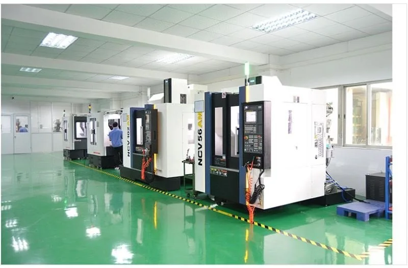
YIOT can support the rigid-part and soft-grip manufacturing routes within one project scope. Agreed deliverables can include DFM review, tooling, molded components, samples for assembly validation, and inspection records. The supply agreement should identify individual plastic parts, subassemblies, or complete assembly work, including responsibility for customer-approved springs, cord, webbing, fasteners, and hooks.
The release package should connect component conformity with the defined mechanism and grip checks. Accepted samples and inspection criteria should identify critical axle, brake, and closure interfaces so subsequent orders can be evaluated consistently. Product load and cycle requirements remain part of the complete-leash validation plan, using the specified hardware and assembly conditions.
Technical references: Celanese’s POM material overview supports screening for sliding and wear-related applications. Avient’s overmolding design guidance discusses material attachment and shrinkage interaction. Material pairing and grip attachment should be reviewed alongside the complete assembly’s load and durability requirements.
Related Capabilities
Discuss Your Project
Share the housing and mechanism models, material requirements, grip expectations, rated-use specification, annual quantity, and assembly test plan. YIOT can assess the rigid-part tooling and the soft-grip manufacturing route together.
An NDA is available. Request a quote or email gerry.li@aiyiot.com. YIOT provides a quotation within 24 hours after receiving complete project information. The DFM review timeline is assessed separately according to project scope.