
Speaker housings and baffles connect the acoustic design with a manufacturable physical assembly. Driver seating, enclosure joints, grille openings, internal ribs, and visible finishes must work together, preserving the intended geometry while supporting consistent molding, assembly, and evaluation of the complete speaker.
Speaker Components
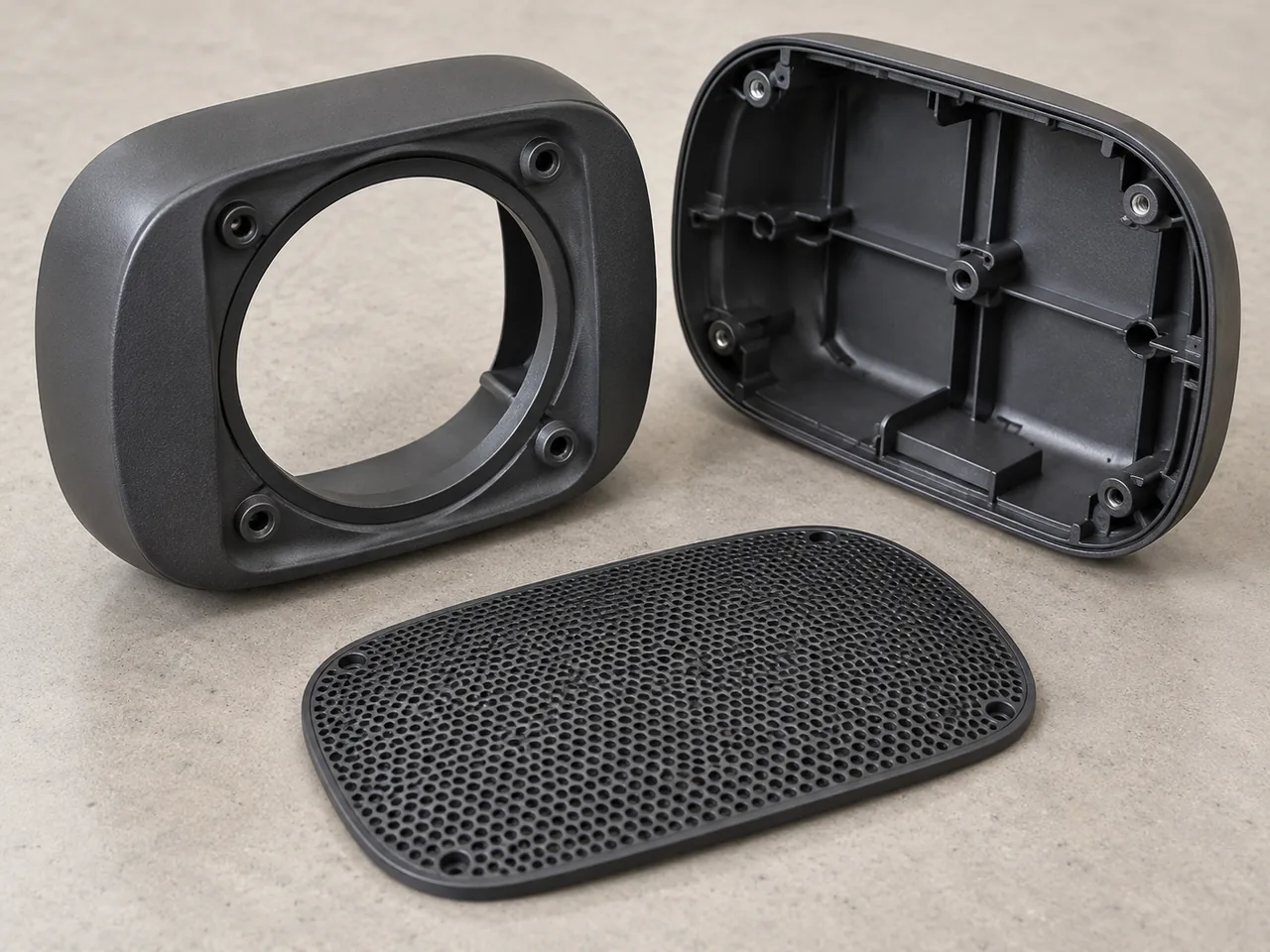
Project Overview
| Application | Molded components for a speaker assembly |
|---|---|
| Project context | Anonymous audio-product application completed by YIOT |
| Engineering priorities | Driver fit, enclosure joints, grille details, and visible finish |
| Recommended Configuration | Material and geometry selected against mechanical and acoustic requirements |
| YIOT capabilities | DFM, mold manufacturing, molding, CNC machining, finishing, and assembly |
Requirements & Engineering Challenges
A molded speaker component can be both a visual surface and part of an acoustic structure. A baffle positions the driver, an enclosure provides the intended internal geometry, and a grille protects components while meeting appearance requirements. The part supplier needs to know which surfaces are cosmetic, which carry mechanical loads, and which belong to the acoustic design so that a routine manufacturing change does not alter an important interface.
The acoustic team should define internal volume, driver position, port geometry where used, joint requirements, and acceptable clearance around moving parts. Mechanical engineering should define fasteners, handling loads, and assembly access. Appearance approval adds color, texture, gloss, and seam expectations. These requirements overlap at the driver mounting ring and enclosure joint, making those areas priorities for the DFM review.
Engineering & Tooling Approach
Select the material against the complete structure
Recommended Configuration: assess a suitable ABS, PC/ABS, or another engineering polymer against impact behavior, finish, stiffness, processing, and any electrical requirements. Filled or specially modified materials may be considered where the design calls for them, but a change in polymer or reinforcement should be reviewed with the acoustic team. A stiffer material does not automatically guarantee better sound in every enclosure.
The material release should identify grade, color, additives, and permitted regrind. Paint, soft-touch layers, decorative films, and printed markings need to be evaluated as additional processes. A coating that meets appearance requirements still needs adhesion and handling checks on the selected substrate. Finishing thickness should be considered around the driver seat, grille clips, and other close-fitting interfaces.
Develop ribs and driver mounting together
Rib placement can support the enclosure and driver mounting region, but thick rib intersections can create sink on the visible surface or distort a seating land. The DFM review should use gradual transitions, cored bosses, and deliberate rib termination. It should also preserve the acoustic volume and avoid placing a rib where it interferes with a driver, wire, gasket, or damping component.
The driver seating ring needs a defined flatness and reference system consistent with its gasket and fastening method. A locally distorted ring can produce uneven contact when the screws are tightened. Screw spacing, pilot geometry, and tightening conditions should be reviewed with the actual hardware. A tolerance should describe the needed function rather than impose a tight number on every surface without a measurement method.
Protect enclosure joints and acoustic features
The joint strategy may use screws, snaps, adhesive, or welding, according to the product design. Each approach creates different molding requirements. A welded joint needs consistent joining geometry and access for the process; an adhesive joint needs suitable lands and material compatibility; a serviceable screw joint needs repeatable seating and fastening. The chosen route should be identified before the mold is finalized.
Ports and other designed air paths must preserve their released dimensions and edge geometry. Gate vestige, ejector marks, and uncontrolled flash should be kept away from these surfaces where practical. If an elastomeric seal or isolation feature is proposed, its compression and attachment need a separate review. Overmolding is an available YIOT process, but its effect on the assembly should be validated for the actual material pair.
Design grille and cosmetic tooling for production
Fine grille openings create repeated narrow steel features, small flow channels, and many potential air traps. Draft, opening geometry, resin flow, and venting should be reviewed together. A pattern that looks suitable in a rendering may need changes for filling and release. The acoustic team should review changes to the open area or geometry rather than treating them as cosmetic edits alone.
Recommended Configuration: use replaceable tool inserts for fine grille details and evolving connector or control openings. Tool steel, cavity count, cooling, and runner design should follow the resin and forecast demand. Textured broad surfaces need appropriate draft, while polished details need a defined appearance standard. Ejection should support the part without marking a visible grille or distorting the driver seat.
- 1. Support rib
Reinforce the enclosure while preserving the released internal geometry and component space. - 2. Mounting land
Coordinate the driver seating ring, screw bosses and any gasket with the actual hardware. - 3. Enclosure seam
Match the joint land to the selected fastening, bonding or welding method. - 4. Grille clearance
Preserve clearance to moving components and review grille changes with the acoustic team.
Manufacturing & Validation
Molding trials should review the enclosure, baffle, and grille as individual parts and in a representative assembly. Dimensional checks can cover driver location, seating profile, joint geometry, port features, and connector or control clearances. Visual checks should identify sink, flow marks, weld lines, texture consistency, edge flash, and finishing damage under agreed conditions.
Assembly validation should use representative drivers, seals, fasteners, damping, and electronics where applicable. The customer’s plan can include air-leak assessment, vibration or rattle checks, acoustic measurements, drop exposure, and environmental conditioning. A nominally correct internal volume does not establish frequency response, and a visually closed seam does not establish an airtight joint. Methods and acceptance limits should come from the speaker requirements and be recorded with the assembly configuration.
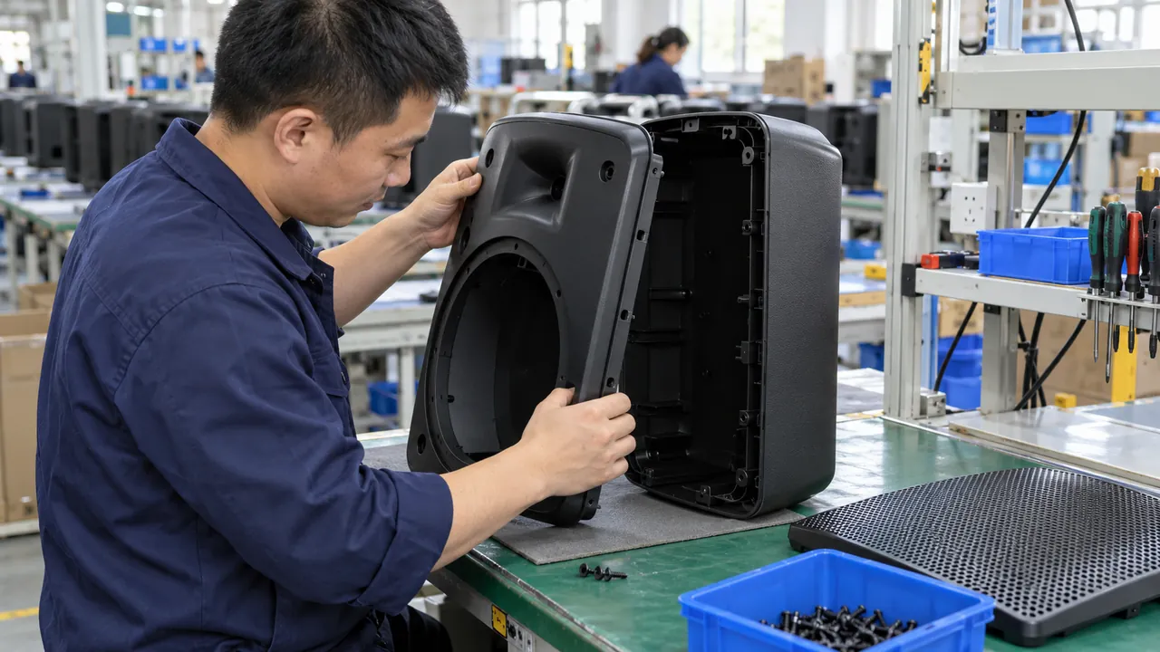
Deliverables & Project Outcome
YIOT can support speaker-component DFM, tooling, molding, and agreed finishing or assembly work. Manufacturing deliverables can include development samples, production components, and inspection records. The supply scope should assign responsibility for driver procurement, electronics, damping materials, acoustic tuning, and final testing so that enclosure manufacture is coordinated with the rest of the product.
The acceptance basis should connect molded geometry and appearance with the agreed complete-speaker checks. Approved samples should capture the driver seat, enclosure joint, grille fit, and any acoustic passage geometry. These controlled interfaces support repeatable assembly and evaluation of the customer’s audio design, with acoustic conclusions based on measurements of the specified complete speaker.
Technical reference: Covestro’s Bayblend material information provides PC/ABS grade options for electrical and consumer applications. It can support polymer screening, but acoustic behavior must be evaluated using the actual enclosure geometry, driver, joints, and complete assembly.
Related Capabilities
Discuss Your Project
Send the enclosure and baffle models, driver interface, grille requirements, joint strategy, cosmetic standard, quantity, and acoustic validation scope. YIOT can assess the molding and finishing route around the features that matter to the complete speaker.
An NDA is available. Request a quote or email gerry.li@aiyiot.com. YIOT provides a quotation within 24 hours after receiving complete project information. The DFM review timeline is assessed separately according to project scope.