
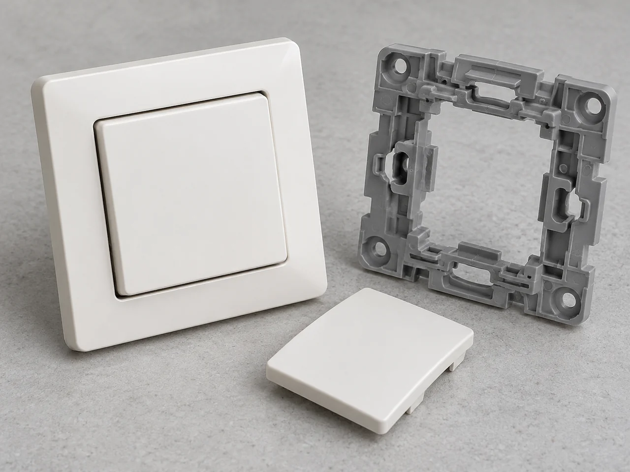
A wall switch panel brings a visible architectural surface together with precise mechanical interfaces. Flatness, color, gloss, snap engagement, and rocker clearance need coordinated control so that the molded panel fits its mechanism, moves as intended, and presents consistent gaps after installation.
Wall Switch Panels
Project Overview
| Application | Molded wall switch panels and trim interfaces |
|---|---|
| Project context | Anonymous electrical-product application completed by YIOT |
| Engineering priorities | Visible flatness, panel gap, snap engagement, and material requirements |
| Recommended Configuration | Grade-specific PC or PC/ABS selected for the product requirements |
| YIOT capabilities | DFM, mold manufacturing, injection molding, finishing, and assembly |
Requirements & Engineering Challenges
Wall switch panels are judged closely because they sit on a plain, visible surface and are touched repeatedly. Small changes in panel bow, corner gap, gloss, or color can be noticeable after installation. At the same time, concealed snaps and locating features must engage the mechanism without distorting the face. The design review should consider the panel, frame, mechanism, and wall interface as one assembly.
Electrical products also place requirements on the material and geometry beyond appearance. The product owner must define applicable market standards, temperature exposure, insulation needs, flammability requirements, and restricted substances. The panel’s role within the electrical assembly determines which checks apply. The manufacturing plan should preserve the selected material identity and drawing requirements rather than treat any white engineering plastic as interchangeable.
Engineering & Tooling Approach
Define the appearance and material release
Recommended Configuration: assess a suitable polycarbonate or PC/ABS grade against impact behavior, temperature, color, and any electrical or flame requirements. The complete grade designation and color must be controlled. A classification obtained for one grade, thickness, or color should not be transferred automatically to a different formulation or a thinner section.
Appearance approval should identify the visible zones, surface finish, permitted gate witness, and viewing conditions. A physical color and gloss standard is more useful than a screen image. If paint, printing, laser marking, or a decorative layer is required, those operations should be reviewed with the substrate and end-use requirements. Coating thickness can also affect small gaps and snap clearances.
Keep rear structures from marking the face
Bosses, ribs, and snap roots on the reverse side can create local section changes that appear as sink or read-through on the front. The DFM review should distribute those structures deliberately, core heavy regions, and avoid abrupt transitions. Increasing the entire panel thickness to hide a local problem may introduce new cooling and warpage concerns rather than resolve the root cause.
The face profile and perimeter gap should be measured from a defined datum system. A free panel and an installed panel can have different shapes because the frame and wall affect support. The drawing should distinguish free-state flatness from installed appearance. Where the design permits, controlled support features can establish seating without forcing the cosmetic face against an uneven background.
Review snap action and mechanism clearance
Snap features should be assessed for deflection during assembly, retention after installation, and removal if the product is serviceable. Tool splits and ejector marks should avoid the snap’s working contact surfaces where practical. Root radii, beam length, material strain behavior, and molding orientation all influence the design; a nominal snap hook is not a complete retention specification.
Rocker panels need adequate clearance through their travel. Paint buildup, flash, panel warp, and an off-center mechanism can each affect movement. Checking only the resting gap can miss interference at full travel. The assembly review should therefore include the intended actuation movement and any adjacent panels in a multi-position frame.
Choose a tooling strategy for the visible surface
Gate position should balance filling with the appearance of the front face and perimeter. Weld lines, jetting, or flow marks can be difficult to remove by polishing if their cause is the filling pattern. Venting must be considered around the final fill region and fine snap details. Cooling should serve the broad panel uniformly enough to support the required shape.
Recommended Configuration: use a mold construction that allows controlled polishing or texturing of the cosmetic cavity and replacement of wear-prone snap details. P20-type prehardened steel, hardened steel, or corrosion-resistant cavity inserts can be evaluated according to finish, resin, volume, and maintenance requirements. Multi-cavity layout should include a plan for cavity-to-cavity appearance and dimensional comparison, not only a nominal production rate.
- 1. Cosmetic face
Protect the visible surface from sink, gate marks and rear feature read-through. - 2. Rear snap
Review clip roots, deflection and release direction with the selected polymer. - 3. Rocker clearance
Coordinate the moving panel with the mechanism and tolerance stack. - 4. Wall interface
Reference the mounting frame and installed face position to the wall interface.
Manufacturing & Validation
The molding process should be developed around the selected resin, color, and finish. Approved samples should identify cavity, revision, and any secondary operation. Cosmetic review needs consistent lighting and handling, while dimensional review needs fixtures that do not conceal distortion. Parts should be protected during transfer and packaging because a compliant molded surface can still be scratched after production.
Inspection can include panel profile, frame gap, snap engagement, rocker movement, visible sink, gloss, color, and edge flash. Assembly checks should use representative mechanism and frame components. Electrical, glow-wire, flammability, heat, or impact testing belongs in the customer-defined product validation plan where applicable. YIOT can align component manufacture with that plan; a visual panel approval does not replace the required electrical-product evaluations.

Deliverables & Project Outcome
YIOT can support panel DFM, mold manufacture, molding, and agreed decoration within a coordinated manufacturing scope. Deliverables can include development samples, production panels, and dimensional or visual inspection records. The quotation should identify any assembly fixture, color variant, printing tool, and packaging requirement so appearance protection is included alongside part manufacture.
Acceptance should connect the visible-panel standard with mechanical fit and the product owner’s compliance requirements. Approved samples should capture color, finish, panel gaps, and mechanism operation under defined assembly conditions. The material identity and component records can then support the complete switch’s qualification and production release, with electrical ratings established through the applicable product evaluations.
Technical references: Covestro’s Bayblend portfolio lists grade-specific material options. UL Solutions explains that plastics flammability evaluation depends on material thickness. A resin classification alone does not certify a completed switch or establish its electrical safety.
Related Capabilities
Discuss Your Project
Send the panel and frame models, mechanism envelope, color and finish standard, market requirements, expected quantity, and assembly acceptance criteria. YIOT can assess cosmetic tooling and functional interfaces as part of the same review.
An NDA is available. Request a quote or email gerry.li@aiyiot.com. YIOT provides a quotation within 24 hours after receiving complete project information. The DFM review timeline is assessed separately according to project scope.