
When sourcing custom injection molds for electronics manufacturing, several technical parameters stand out as decisive factors. Wall thickness, typically ranging from 1.2 to 3 mm for most plastics, is critical in determining the strength and performance of the molded part. Uniformity within manageable variation (about 10-25%) ensures dimensional accuracy and prevents defects. Draft angles, with a minimum of 1° for smooth faces, play a pivotal role in mold release, avoiding damage during ejection. Companies must also consider tolerances, as specified by ISO 20457:2026, for acceptable geometrical precision. Ignoring these metrics could lead to costly errors and inefficiencies. Therefore, a thorough understanding of these dimensions and their impact on mold design is crucial for successful electronic component production. By focusing on these factors, manufacturers can significantly enhance the reliability and functionality of electronic components.
Key takeaways
- In the precise world of custom injection molding for electronics, a few critical numbers dictate mold quality.
- Wall thickness is a critical parameter in injection molding, significantly influencing the outcome of a molded part.
- Draft angles play a crucial role in the smooth ejection of plastic parts from molds.
- Tolerances are defined as the permissible limits of variation in a physical dimension, and they are critical to the function and manufacturability of a product.
- When evaluating a supplier’s data sheet, it’s crucial to know which metrics are key indicators of mold performance and quality for electronics manufacturing.
The Handful of Numbers That Decide Mold Quality
In the precise world of custom injection molding for electronics, a few critical numbers dictate mold quality.
Understanding these metrics leads to reliable mold performance, which is vital for maintaining consistency and functionality across high-volume production runs.
Wall Thickness and Tolerances
The nominal wall thickness for plastics such as ABS and PC in electronics typically ranges from 1.2 mm to 4.0 mm. For electronics, it’s crucial to maintain this uniformity to avoid warping and cooling issues. Maintaining a variation under approximately 10% to 25% is standard practice. However, when working with complex geometries, these parameters can become challenging. Therefore, layers of quality checks combined with robust design verification practices are essential to manage these parameters effectively throughout the production pipeline.
ISO 20457 is the standard frequently referred to when specifying tolerances for injection-molded parts. This standard underlines the permissible variation in wall thickness, ensuring parts consistently fit and function as intended. Despite not being certified for ISO 20457, it is advisable for buyers sourcing electronics molds to ensure compliance with this standard to prevent costly deviations in high-volume production.
Draft Angles for Mold Release
Draft angles prevent damage during ejection and promote smooth release from the mold. For most electronics molds, a minimum draft angle of 1° per side is recommended. As the texture and depth of the mold increase, draft angles require proportional adjustments. Inconsistent draft angles lead to issues such as ejection marks and part deformation, which compromise the mold’s quality. Collaboration with suppliers to evaluate specific texture requirements can refine these angles and enhance smooth ejection processes.

Importance of Uniformity
Consistency and accuracy in mold production are crucial, specifically in the electronics sector. Variations in wall thickness, draft angles, or tolerances can result in defects impacting the durability and fit of electronic components. Ensuring uniformity across all these dimensions mitigates risk and enhances the performance of the final product. Implementing stringent quality assurance protocols allows for consistent checks to uphold this uniformity.
Numerical Standards in Electronics Molds
Metrics such as draft angles and wall thickness not only improve mold ejection and part reliability but also reduce defective rates. These measurements ensure that parts consistently meet tight specifications needed for the demanding electronics field. Working with experienced mold designers can further cement adherence to these critical metrics, ensuring optimal mold functionality.
Critical Metrics in Injection Mold Quality
| Metric | Typical Range | Relevance |
|---|---|---|
| Wall Thickness | 1.2–4.0 mm | Critical for preventing warping and maintaining strength |
| Tolerances | Per ISO 20457 | Essential for part consistency across production runs |
| Draft Angles | ≥1° per side | Ensures smooth ejection without damage |
| Uniformity | Variation < 10%-25% | Crucial for accuracy and function |
Understanding these numbers is indispensable for anyone involved in the production of electronic components. Consequently, actionable awareness of these aspects ensures precision and quality in every molded part produced.
Wall Thickness: Its Importance and Measurement
Wall thickness is a critical parameter in injection molding, significantly influencing the outcome of a molded part.
For most plastics, standard wall thickness ranges from 1.2 to 3 mm, with material-specific variations such as 1.2 to 3.5 mm for ABS and 1.0 to 4.0 mm for PC. Achieving these standards impacts everything from material usage to the quality of the final product. Inconsistent wall thickness can lead to issues like warping, sink marks, or increased cycle times, hence maintaining uniformity is crucial.
Measuring Wall Thickness
Measuring wall thickness is primarily conducted through non-destructive methods such as ultrasonic testing or laser scanning, allowing precision without compromising the part’s integrity. These methods provide accurate dimensional checks, essential for ensuring consistent mold filling and structural integrity. Despite sophisticated measurement tools, manual errors often creep in, thus regular calibration of measuring devices is vital to maintain accuracy. Additionally, integrating automated quality control systems can significantly enhance the reliability and speed of these measurements.
Effects on Mold Performance
Uniform wall thickness ensures a consistent flow of molten plastic during the injection process, minimizing defects. Thicker walls require longer cooling times, impacting production efficiency. In contrast, walls that are too thin may not provide the necessary rigidity, potentially leading to part deformation or mechanical failure under stress. Therefore, precise calculation of wall thickness is necessary for balancing performance, aesthetics, and material costs. Understanding the relationship between part function and wall thickness aids in effective decision-making during the design process.
Tolerances and Uniformity Maintenance
Maintaining wall thickness within specified tolerances is an engineering challenge. Generally, a variation of around 10-25% is acceptable, but this depends on the part’s design and intended application. The ISO standards guide manufacturers on acceptable tolerances, though individual project requirements can vary. Minor deviations can be addressed through mold design adjustments, but consistently achieving uniformity demands meticulous attention to tooling and mold maintenance. Implementing a robust quality management system helps minimize these deviations and uphold consistency.
Challenges in Uniformity
Achieving a consistent wall thickness across complex components with varying shapes is challenging. Factors such as tool wear, injection pressure variations, and temperature fluctuations can introduce inconsistencies. Regular maintenance of tooling equipment, the use of advanced simulation techniques during mold design, and adherence to stringent quality checks are imperative practices to mitigate these challenges effectively. Emphasizing predictive maintenance through IoT solutions can preemptively address potential issues before they affect production.
Draft Angles: Ensuring Smooth Part Ejection
Draft angles play a crucial role in the smooth ejection of plastic parts from molds.
Inadequate draft design often leads to issues such as part sticking or ejection damage. For electronics molds, especially those used in enclosures, maintaining specified draft angles ensures minimal defects and enhances production efficiency.
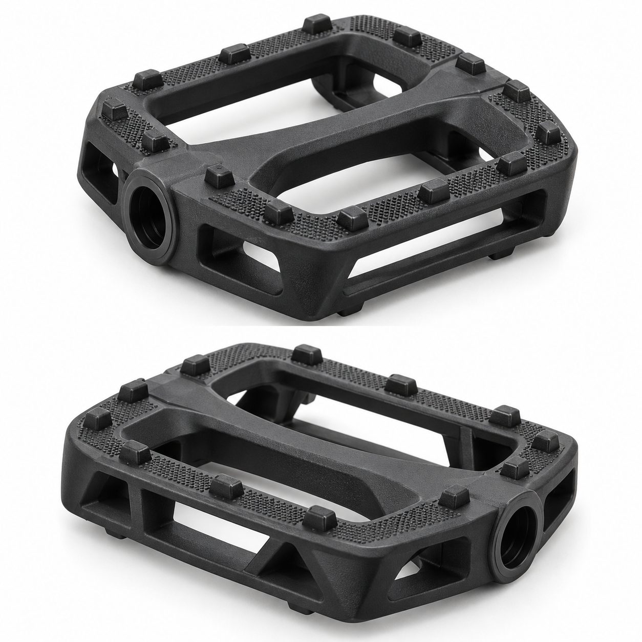
A basic rule for injection molds is that vertical faces should typically have a minimum draft angle of 1 degree per side. This facilitates the release of molded parts without sticking or causing damage, particularly when dealing with thermoplastic materials like ABS and PC. Precise measuring of these angles can be accomplished using goniometers or calibrated protractors. Additionally, utilizing CAD software during the design phase allows for virtual testing and optimization of these angles to accommodate specific project needs.
Draft Angle Specifications
| Surface Type | Minimum Draft Angle | Why It Matters |
|---|---|---|
| Smooth | 0.5-1° | Ensures ejection without damage or sticking |
| Light Texture | ~3° | Accommodates texture depth to prevent drag marks |
| Heavy Texture | 5-7° | Prevents tearing or deformation of detailed surfaces |
| Curved Features | ≥1° | Facilitates easy release from complex shapes |
Draft angles must account for the surface finish of the part. For instance, lightly textured surfaces require at least a 3-degree draft to allow for the texture depth, ensuring the surface remains free of drag marks after ejection. More robust textures, such as those intended for heavy grip areas on electronic enclosures, will necessitate 5 to 7 degrees of draft to prevent tearing during part removal.
Additionally, when specifying draft angles, one must consider issues such as parting line precision and its potential impact on the cosmetic appearance of critical areas. With electronic components, achieving high precision is vital, and small inaccuracies can lead to assembly issues or malfunction. Incorporating advanced metrology tools in the post-production phase can ensure adherence to these precise specifications.
We recommend checking out our Custom Injection Molds for Plastic Consumer Electronics Enclosures for examples of expertly designed molds that account for these factors.
Furthermore, the design phase should incorporate potential adjustments for complex geometries or unique design features. A failure to adequately plan for draft angles can lead to a multitude of problems, from increased cycle times to compromised part integrity. As a result, careful specification of draft angles at the design stage is critical to the mold’s success and the overall quality of the final product. This foresight is paramount in ensuring that molding cycles are efficient and that product designs are optimized for scalability.
Tolerance: The Often Overlooked Metric
Tolerances are defined as the permissible limits of variation in a physical dimension, and they are critical to the function and manufacturability of a product.
For custom injection molds, particularly in electronics manufacturing, tolerances ensure that every unit produced meets the precise requirements necessary for proper assembly and function. Without clearly defined tolerances, the risk of parts not fitting together or failing to perform as intended increases significantly.
Specifying tolerances in design begins with a thorough understanding of both the part’s functional requirements and the capabilities of the manufacturing process. Designers must collaborate closely with manufacturers to set realistic and achievable tolerances that account for factors like material properties and processing conditions. For electronic components, tolerances typically need to be within tight ranges due to the precision fitting required in assemblies. A tolerance of ±0.05 mm is common for intricate electronics parts to ensure alignment and connectivity. The integration of tolerance analysis software can further optimize this process by predicting potential problem areas before physical production.

Typical tolerances can vary widely based on material and application. For plastics like ABS, tolerances might range anywhere from ±0.1 to ±0.5 mm, while more flexible materials like rubber may allow for greater deviation. These tolerances are often linked closely with ISO 20457, a standard that provides guidelines on geometrical and dimensional tolerances in injection-molded plastic parts. Compliance with such standards ensures that parts not only fit together but also adhere to global industry benchmarks, a vital factor in international trade.
Ignoring or providing inadequate tolerances can result in numerous issues. For example, too-tight tolerances might increase production costs and result in rejected parts due to difficulties in maintaining specified dimensions. Conversely, too loose tolerances can lead to parts that fail to fit or function correctly. Both scenarios can result in costly delays and a significant impact on a project’s timeline and budget.
In summary, tolerances are not merely numbers on a drawing but rather critical specifications that directly affect the outcome of the manufacturing process. Therefore, understanding and specifying correct tolerances as per industry standards like ISO 20457 not only prevent functional failures but also streamline production by minimizing errors and rework. For precision-dependent industries, particularly electronics, paying attention to this often-overlooked metric is essential to maintaining competitive and functional product lines. Regular feedback loops with quality assurance teams ensure that any tolerance deviations are quickly addressed, maintaining high-performance standards.
Reading Supplier’s Data Sheets: Essential Tips
When evaluating a supplier’s data sheet, it’s crucial to know which metrics are key indicators of mold performance and quality for electronics manufacturing.
Focus on both standardized specifications and supplier-specific terminology, as these elements can significantly impact the suitability of a mold for your needs.
Key Metrics to Locate
A buyer should pay attention to specific metrics that define the functional capabilities of a mold:
- Material Grade and Shrinkage Rates: Each plastic material has specific shrinkage values. For instance, ABS typically ranges from 0.4-0.7%, while PC is usually between 0.5-0.7%. Knowing these figures helps predict dimensional changes during cooling.
- Wall Thickness and Draft Details: Data sheets should clearly detail standard wall thickness (usually 1.2–3 mm for most plastics) and recommended draft angles, as these affect part accuracy and ejection ease.
- Tolerances and Dimensional Standards: Look for compliance with benchmarks like ISO 20457, which details dimensional tolerances for injection-molded parts, although always verify if specific to this company, as they currently hold ISO 9001:2015. For added assurance, request technical discussions with the supplier to validate these compliance claims.
Decoding Technical Terms and Specifications
Data sheets often include industry jargon that can be daunting. Understanding these terms is important:
- Rib and Boss Design: The thickness of ribs (40–60% of wall thickness) and the size of bosses (often 2× screw major diameter) must align with your design needs to prevent issues like warping.
- Surface Finish Levels: Standards like SPI A-1 to D-3 describe finishes from mirror polish (Ra ≈ 0.012–0.05 µm) to heavy texture (Ra ≈ 0.8–3.2 µm).
Common Red Flags in Data Sheets
Occasional discrepancies or lack of information can indicate potential issues:
- Incomplete Material Specifications: Missing resin grades can lead to performance mismatches.
- Inaccurately Tight Tolerances: Over-specification can suggest unrealistic promises or potential cost hikes without value.
Understanding Supplier-Specific Terminology
Suppliers might use unique terms for processes or components. It’s vital to seek clarification to avoid misunderstandings. Engaging in supplier workshops can promote mutual understanding and prevent specification miscommunication.
Verification Methods for Reported Data
To ensure the credibility of a supplier’s specs, consider the following approaches:
- Third-party Verification: Engage third-party testing for critical specs, especially for initial samples or new suppliers. This can offer independent validation of a supplier’s technical data.
- Historical Performance: Request case studies or testimonials showcasing the supplier’s adherence to specifications over past projects. Insight into real-world applications can provide confidence in a supplier’s capabilities.
Decoding Supplier Data Sheets
| Element | What to Look For | Importance |
|---|---|---|
| Material Specs | Complete grade and shrinkage information | Ensures compatibility and performance predictability |
| Wall Thickness | Defined nominal values consistent with part design | Affects strength, cooling efficiency, and cost |
| Tolerance Specs | Clearly stated limits per industry norms | Determines part accuracy and fit |
| Surface Finish | SPI standard indications with precise measurement | Impacts aesthetic and functional surface properties |
| Draft Angles | Specific minimums for texture and part complexity | Facilitates effective part ejection, preventing damage |
Evaluating a supplier’s data sheet requires a deep understanding of the listed specifications and their implications on your product design and cost. This understanding can help navigate technical negotiations and identify the best supplier fit for your project.
Common Mistakes Buyers Make in Specifications
Highlighting common pitfalls in creating specifications for injection molds can save both time and resources.
One typical error is over-specifying unnecessary features. Buyers often mistake adding features that sound beneficial, but these can complicate the mold-making process without adding tangible value, leading to increased costs and potential issues down the line.
Another frequent misstep is failing to define clear wall thickness and draft angles. A lack of clarity here can lead to significant molding issues. Correct wall thickness is crucial, as it influences everything from mold cooling times to the overall strength and durability of the plastic part. Draft angles, on the other hand, are essential for ensuring that parts eject smoothly from the mold without damage. Omitting precise specifications for these elements often results in defects such as warpage or ejection marks. Regular updates to design documentation, incorporating feedback from previous production runs, can streamline specification clarity and correctness.
Ignoring necessary tolerances is another critical mistake. Injection molded parts require tight tolerances to meet functional and aesthetic requirements. However, buyers sometimes neglect to specify these tolerances accurately, or they over-specify unnecessary tight tolerances, which only escalate machining and tooling costs. Accurate tolerances should align with set standards, striking a balance between performance needs and cost efficiency.

Miscommunication with suppliers is also a prevalent issue. A successful procurement process hinges on clear, precise communication between the buyer and the supplier. Designers and engineers should ensure that their instructions are unequivocal and accompanied by detailed CAD models and specification sheets. Misunderstandings often arise from vague or incomplete documentation, leading to molds that may not meet all design requirements. Facilitating regular supplier meetings to discuss and finalize specification details can profoundly improve communication channels.
Finally, neglecting undercut complexities can complicate mold design unnecessarily. Undercuts often require more intricate tooling solutions, like side actions or lifters, which increase mold complexity and cost. It’s vital to assess whether these features can be designed out or minimized to simplify the molding process. Reconsidering part designs to eliminate unnecessary undercuts can drastically simplify production and reduce costs. Leveraging advanced design software can help identify these features early in the design phase, allowing for modifications that align with manufacturing capabilities efficiently.
Understanding these common specification errors and working closely with experienced suppliers like Yiot Technology Co., Ltd. can mitigate these risks. This approach ensures more consistent production quality and lessens costly errors. Being proactive in creating precise and well-considered specifications is the key to a successful project and a partnership that executes efficiently.
Conclusion: Making the Right Mold Decision
Comprehensive specifications form the backbone of effective mold-making partnerships.
By focusing on key metrics and informed decision-making, you enhance product quality and optimize manufacturing processes. Collaborating closely with suppliers ensures adherence to specific design requirements, tailoring them to suit your project needs. Evaluating supplier capabilities with a clear set of metrics allows for seamless integration into your production flow, simplifying the path from concept to reality. Incorporating feedback loops and iterative development strategies can further refine these specifications over time, ensuring sustained product excellence. Let us evaluate your sample, drawing, or specification to provide insights that align with your objectives efficiently.
Frequently asked questions
What should I consider when specifying mold dimensions?
Consider wall thickness, draft angles, and adherence to tolerance standards like ISO 20457. Ensure all specifications align with the intended function of the part and manufacturing capabilities. It’s crucial to integrate these factors with the overall product design, considering both material restrictions and desired final aesthetics. Properly defined dimensions ensure compatibility across the production chain, from initial design to final assembly.
How do I ensure my supplier meets ISO standards?
Verify their certification status for standards such as ISO 9001:2015. Review their data sheets and request evidence of compliance with specific ISO metrics relevant to your product. Liaising directly with your supplier to establish explicit compliance documentation and feedback can aid in maintaining these standards. Additionally, periodic assessments through audits and inspections can reinforce adherence to the required standards persistently. Ensuring that both manufacturing environments and practices align with global best practices is pivotal in achieving sustained product quality.
Request a project review
Send the 3D model, 2D drawing, material requirements, annual volume and critical dimensions. The team will identify open technical questions before tooling is quoted.